

3.3 Merits of Introducing Superconductivity
39
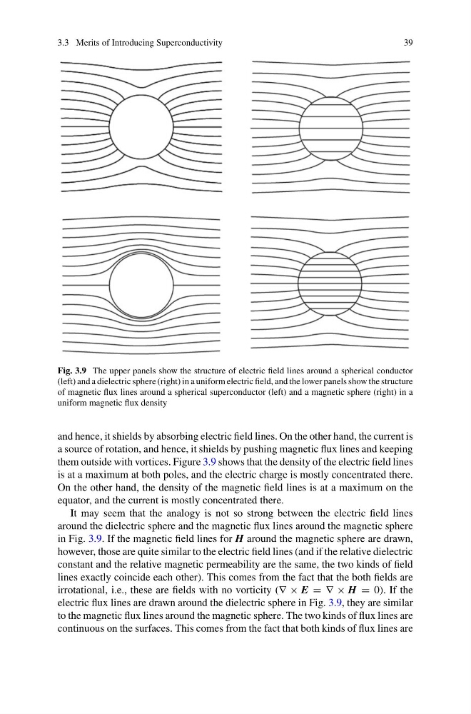
Fig. 3.9 The upper panels show the structure of electric field lines around a spherical conductor
(left) and a dielectric sphere (right) in a uniform electric field, and the lower panels show the structure
of magnetic flux lines around a spherical superconductor (left) and a magnetic sphere (right) in a
uniform magnetic flux density
and hence, it shields by absorbing electric field lines. On the other hand, the current is
a source of rotation, and hence, it shields by pushing magnetic flux lines and keeping
them outside with vortices. Figure 3.9 shows that the density of the electric field lines
is at a maximum at both poles, and the electric charge is mostly concentrated there.
On the other hand, the density of the magnetic field lines is at a maximum on the
equator, and the current is mostly concentrated there.
It may seem that the analogy is not so strong between the electric field lines
around the dielectric sphere and the magnetic flux lines around the magnetic sphere
in Fig. 3.9. If the magnetic field lines for H around the magnetic sphere are drawn,
however, those are quite similar to the electric field lines (and if the relative dielectric
constant and the relative magnetic permeability are the same, the two kinds of field
lines exactly coincide each other). This comes from the fact that the both fields are
irrotational, i.e., these are fields with no vorticity (∇ × E = ∇ × H = 0). If the
electric flux lines are drawn around the dielectric sphere in Fig. 3.9, they are similar
to the magnetic flux lines around the magnetic sphere. The two kinds of flux lines are
continuous on the surfaces. This comes from the fact that both kinds of flux lines are
39
Fig. 3.9 The upper panels show the structure of electric field lines around a spherical conductor
(left) and a dielectric sphere (right) in a uniform electric field, and the lower panels show the structure
of magnetic flux lines around a spherical superconductor (left) and a magnetic sphere (right) in a
uniform magnetic flux density
and hence, it shields by absorbing electric field lines. On the other hand, the current is
a source of rotation, and hence, it shields by pushing magnetic flux lines and keeping
them outside with vortices. Figure 3.9 shows that the density of the electric field lines
is at a maximum at both poles, and the electric charge is mostly concentrated there.
On the other hand, the density of the magnetic field lines is at a maximum on the
equator, and the current is mostly concentrated there.
It may seem that the analogy is not so strong between the electric field lines
around the dielectric sphere and the magnetic flux lines around the magnetic sphere
in Fig. 3.9. If the magnetic field lines for H around the magnetic sphere are drawn,
however, those are quite similar to the electric field lines (and if the relative dielectric
constant and the relative magnetic permeability are the same, the two kinds of field
lines exactly coincide each other). This comes from the fact that the both fields are
irrotational, i.e., these are fields with no vorticity (∇ × E = ∇ × H = 0). If the
electric flux lines are drawn around the dielectric sphere in Fig. 3.9, they are similar
to the magnetic flux lines around the magnetic sphere. The two kinds of flux lines are
continuous on the surfaces. This comes from the fact that both kinds of flux lines are