

136
6 Longitudinal Magnetic Field Effect
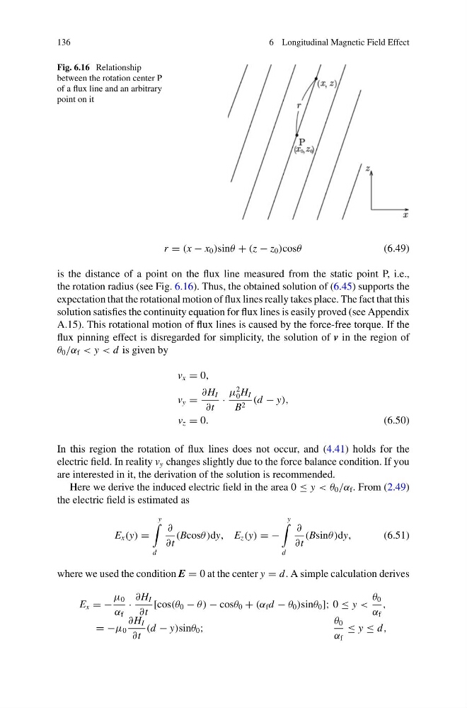
Fig. 6.16 Relationship
between the rotation center P
of a flux line and an arbitrary
point on it
r = (x − x 0 )sinθ + (z − z 0 )cosθ
(6.49)
is the distance of a point on the flux line measured from the static point P, i.e.,
the rotation radius (see Fig. 6.16). Thus, the obtained solution of (6.45) supports the
expectation that the rotational motion of flux lines really takes place. The fact that this
solution satisfies the continuity equation for flux lines is easily proved (see Appendix
A.15). This rotational motion of flux lines is caused by the force-free torque. If the
flux pinning effect is disregarded for simplicity, the solution of v in the region of
θ 0 /α f < y < d is given by
v x = 0,
v y =
∂H I
∂t
·
μ
2
0 H I
B 2 (d − y),
v z = 0.
(6.50)
In this region the rotation of flux lines does not occur, and (4.41) holds for the
electric field. In reality v y changes slightly due to the force balance condition. If you
are interested in it, the derivation of the solution is recommended.
Here we derive the induced electric field in the area 0 ≤ y < θ 0 /α f . From (2.49)
the electric field is estimated as
E x (y) =
y
d
∂
∂t
(Bcosθ )dy, E z (y) = −
y
d
∂
∂t
(Bsinθ )dy,
(6.51)
where we used the condition E = 0 at the center y = d . A simple calculation derives
E x = −
μ 0
α f
·
∂H I
∂t
[cos(θ 0 − θ ) − cosθ 0 + (α f d − θ 0 )sinθ 0 ]; 0 ≤ y <
θ 0
α f
,
= −μ 0
∂H I
∂t
(d − y)sinθ 0 ;
θ 0
α f
≤ y ≤ d ,
6 Longitudinal Magnetic Field Effect
Fig. 6.16 Relationship
between the rotation center P
of a flux line and an arbitrary
point on it
r = (x − x 0 )sinθ + (z − z 0 )cosθ
(6.49)
is the distance of a point on the flux line measured from the static point P, i.e.,
the rotation radius (see Fig. 6.16). Thus, the obtained solution of (6.45) supports the
expectation that the rotational motion of flux lines really takes place. The fact that this
solution satisfies the continuity equation for flux lines is easily proved (see Appendix
A.15). This rotational motion of flux lines is caused by the force-free torque. If the
flux pinning effect is disregarded for simplicity, the solution of v in the region of
θ 0 /α f < y < d is given by
v x = 0,
v y =
∂H I
∂t
·
μ
2
0 H I
B 2 (d − y),
v z = 0.
(6.50)
In this region the rotation of flux lines does not occur, and (4.41) holds for the
electric field. In reality v y changes slightly due to the force balance condition. If you
are interested in it, the derivation of the solution is recommended.
Here we derive the induced electric field in the area 0 ≤ y < θ 0 /α f . From (2.49)
the electric field is estimated as
E x (y) =
y
d
∂
∂t
(Bcosθ )dy, E z (y) = −
y
d
∂
∂t
(Bsinθ )dy,
(6.51)
where we used the condition E = 0 at the center y = d . A simple calculation derives
E x = −
μ 0
α f
·
∂H I
∂t
[cos(θ 0 − θ ) − cosθ 0 + (α f d − θ 0 )sinθ 0 ]; 0 ≤ y <
θ 0
α f
,
= −μ 0
∂H I
∂t
(d − y)sinθ 0 ;
θ 0
α f
≤ y ≤ d ,