

12.2 Analysis of the Crystalline Structure 283
the differentiation between the cubic and the tetragonal structure, where, because
of the line broadening, the typical splitting of the lines is no longer observable.
Diffraction experiments using X-rays are performed, generally, in reflection,
whereas electron diffraction is performed nearly exclusively in transmission. The
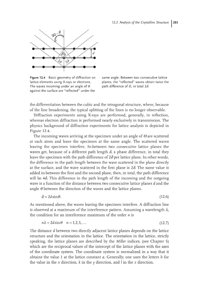
physics background of diffraction experiments for lattice analysis is depicted in
Figure 12.4.
The incoming waves arriving at the specimen under an angle of Θ are scattered
at each atom and leave the specimen at the same angle. The scattered waves
leaving the specimen interfere. In-between two consecutive lattice planes the
waves get, because of a different path length δ, a phase difference, in total they
leave the specimen with the path difference of 2δ per lattice plane. In other words,
the difference in the path length between the wave scattered in the plane directly
at the surface, and the wave scattered in the first plane is 2δ. The same value is
added in-between the first and the second plane, then, in total, the path difference
will be 4δ. This difference in the path length of the incoming and the outgoing
wave is a function of the distance between two consecutive lattice planes d and the
angle θ between the direction of the waves and the lattice planes.
δ
θ
= 2d sin .
(12.6)
As mentioned above, the waves leaving the specimen interfere. A diffraction line
is observed at a maximum of the interference pattern. Assuming a wavelength λ,
the condition for an interference maximum of the order n is
n
d
n
λ
θ
=
=
2
1 2 3
sin
, , , .
…
(12.7)
The distance d between two directly adjacent lattice planes depends on the lattice
structure and the orientation in the lattice. The orientation in the lattice, strictly
speaking, the lattice planes are described by the Miller indices, (see Chapter 5)
which are the reciprocal values of the intercept of the lattice planes with the axes
of the coordinate system. The coordinate system is normalized in a way that it
obtains the value 1 at the lattice constant a. Generally; one uses the letters h for
the value in the x direction, k in the y direction, and l in the z direction.
Figure 12.4 Basic geometry of diffraction on
lattice elements using X-rays or electrons.
The waves incoming under an angle of θ
against the surface are “reflected” under the
same angle. Between two consecutive lattice
planes, the “reflected” waves obtain twice the
path difference of δ.; in total 2δ.
δ
d
–
the differentiation between the cubic and the tetragonal structure, where, because
of the line broadening, the typical splitting of the lines is no longer observable.
Diffraction experiments using X-rays are performed, generally, in reflection,
whereas electron diffraction is performed nearly exclusively in transmission. The
physics background of diffraction experiments for lattice analysis is depicted in
Figure 12.4.
The incoming waves arriving at the specimen under an angle of Θ are scattered
at each atom and leave the specimen at the same angle. The scattered waves
leaving the specimen interfere. In-between two consecutive lattice planes the
waves get, because of a different path length δ, a phase difference, in total they
leave the specimen with the path difference of 2δ per lattice plane. In other words,
the difference in the path length between the wave scattered in the plane directly
at the surface, and the wave scattered in the first plane is 2δ. The same value is
added in-between the first and the second plane, then, in total, the path difference
will be 4δ. This difference in the path length of the incoming and the outgoing
wave is a function of the distance between two consecutive lattice planes d and the
angle θ between the direction of the waves and the lattice planes.
δ
θ
= 2d sin .
(12.6)
As mentioned above, the waves leaving the specimen interfere. A diffraction line
is observed at a maximum of the interference pattern. Assuming a wavelength λ,
the condition for an interference maximum of the order n is
n
d
n
λ
θ
=
=
2
1 2 3
sin
, , , .
…
(12.7)
The distance d between two directly adjacent lattice planes depends on the lattice
structure and the orientation in the lattice. The orientation in the lattice, strictly
speaking, the lattice planes are described by the Miller indices, (see Chapter 5)
which are the reciprocal values of the intercept of the lattice planes with the axes
of the coordinate system. The coordinate system is normalized in a way that it
obtains the value 1 at the lattice constant a. Generally; one uses the letters h for
the value in the x direction, k in the y direction, and l in the z direction.
Figure 12.4 Basic geometry of diffraction on
lattice elements using X-rays or electrons.
The waves incoming under an angle of θ
against the surface are “reflected” under the
same angle. Between two consecutive lattice
planes, the “reflected” waves obtain twice the
path difference of δ.; in total 2δ.
δ
d
–