

6. Calibrate the Z axis (Fig. 6): bring the build surface to the
nozzle and save as zero height the position where the tape just
starts to pinch.
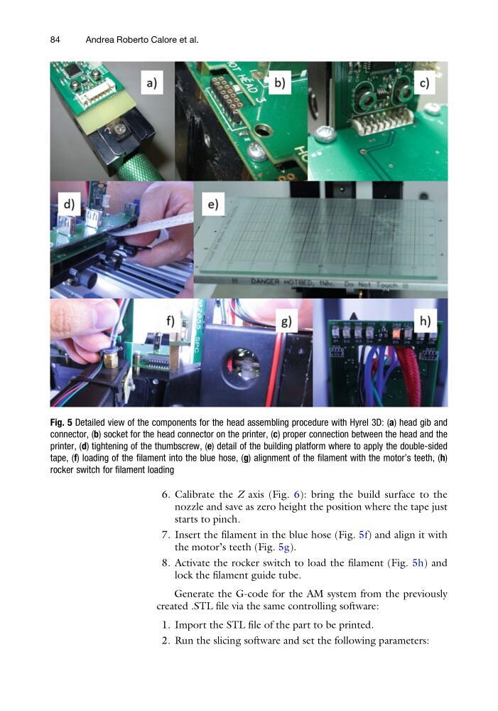
7. Insert the filament in the blue hose (Fig. 5f) and align it with
the motor’s teeth (Fig. 5g).
8. Activate the rocker switch to load the filament (Fig. 5h) and
lock the filament guide tube.
Generate the G-code for the AM system from the previously
created .STL file via the same controlling software:
1. Import the STL file of the part to be printed.
2. Run the slicing software and set the following parameters:
Fig. 5 Detailed view of the components for the head assembling procedure with Hyrel 3D: (a) head gib and
connector, (b) socket for the head connector on the printer, (c) proper connection between the head and the
printer, (d) tightening of the thumbscrew, (e) detail of the building platform where to apply the double-sided
tape, (f) loading of the filament into the blue hose, (g) alignment of the filament with the motor’s teeth, (h)
rocker switch for filament loading
84
Andrea Roberto Calore et al.
nozzle and save as zero height the position where the tape just
starts to pinch.
7. Insert the filament in the blue hose (Fig. 5f) and align it with
the motor’s teeth (Fig. 5g).
8. Activate the rocker switch to load the filament (Fig. 5h) and
lock the filament guide tube.
Generate the G-code for the AM system from the previously
created .STL file via the same controlling software:
1. Import the STL file of the part to be printed.
2. Run the slicing software and set the following parameters:
Fig. 5 Detailed view of the components for the head assembling procedure with Hyrel 3D: (a) head gib and
connector, (b) socket for the head connector on the printer, (c) proper connection between the head and the
printer, (d) tightening of the thumbscrew, (e) detail of the building platform where to apply the double-sided
tape, (f) loading of the filament into the blue hose, (g) alignment of the filament with the motor’s teeth, (h)
rocker switch for filament loading
84
Andrea Roberto Calore et al.