

independent directions and can be infinitely reproduced by repetition of cubic translational unit cells and thus can be used to construct a 3D porous scaffold.
1. Each TPMS design is defined by a trigonometric equation that
is closely approximated by a periodic nodal surface [12] which
leads to bicontinuous (or biphasic) TPMS porous structures.
Figure 1 lists the approximated periodic nodal equations for
five TPMS structures. Such approximation allows designing
TPMS architectures, which therefore can form a solid/void
interface where the void space represents the pores of the 3D
scaffold and the solid space is materialized by the polymer.
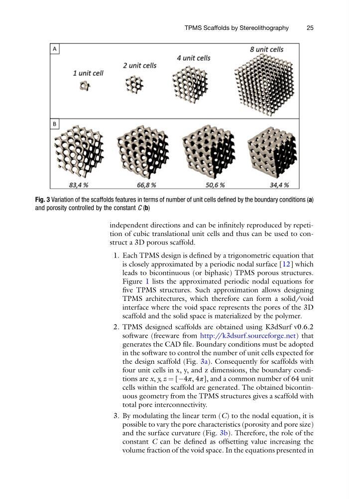
2. TPMS designed scaffolds are obtained using K3dSurf v0.6.2
software (freeware from http://k3dsurf.sourceforge.net) that
generates the CAD file. Boundary conditions must be adopted
in the software to control the number of unit cells expected for
the design scaffold (Fig. 3a). Consequently for scaffolds with
four unit cells in x, y, and z dimensions, the boundary conditions are x, y, z ¼ [À4π, 4π], and a common number of 64 unit
cells within the scaffold are generated. The obtained bicontinuous geometry from the TPMS structures gives a scaffold with
total pore interconnectivity.
3. By modulating the linear term (C) to the nodal equation, it is
possible to vary the pore characteristics (porosity and pore size)
and the surface curvature (Fig. 3b). Therefore, the role of the
constant C can be defined as offsetting value increasing the
volume fraction of the void space. In the equations presented in
Fig. 3 Variation of the scaffolds features in terms of number of unit cells defined by the boundary conditions (a)
and porosity controlled by the constant C (b)
TPMS Scaffolds by Stereolithography
25
1. Each TPMS design is defined by a trigonometric equation that
is closely approximated by a periodic nodal surface [12] which
leads to bicontinuous (or biphasic) TPMS porous structures.
Figure 1 lists the approximated periodic nodal equations for
five TPMS structures. Such approximation allows designing
TPMS architectures, which therefore can form a solid/void
interface where the void space represents the pores of the 3D
scaffold and the solid space is materialized by the polymer.
2. TPMS designed scaffolds are obtained using K3dSurf v0.6.2
software (freeware from http://k3dsurf.sourceforge.net) that
generates the CAD file. Boundary conditions must be adopted
in the software to control the number of unit cells expected for
the design scaffold (Fig. 3a). Consequently for scaffolds with
four unit cells in x, y, and z dimensions, the boundary conditions are x, y, z ¼ [À4π, 4π], and a common number of 64 unit
cells within the scaffold are generated. The obtained bicontinuous geometry from the TPMS structures gives a scaffold with
total pore interconnectivity.
3. By modulating the linear term (C) to the nodal equation, it is
possible to vary the pore characteristics (porosity and pore size)
and the surface curvature (Fig. 3b). Therefore, the role of the
constant C can be defined as offsetting value increasing the
volume fraction of the void space. In the equations presented in
Fig. 3 Variation of the scaffolds features in terms of number of unit cells defined by the boundary conditions (a)
and porosity controlled by the constant C (b)
TPMS Scaffolds by Stereolithography
25