

For the numerical computation of the shear stress (Fig. 8b), a
uniform displacement in a single direction is considered (the Y
direction), which is equivalent to the strain on the same direction
(γxy), imposed to a face of the block (Face B). The opposite face
(Face A) of the scaffold unit is constrained and unable to have any
displacement. The two lateral faces (Faces C) are also constrained
and unable to have any displacement in the X direction.
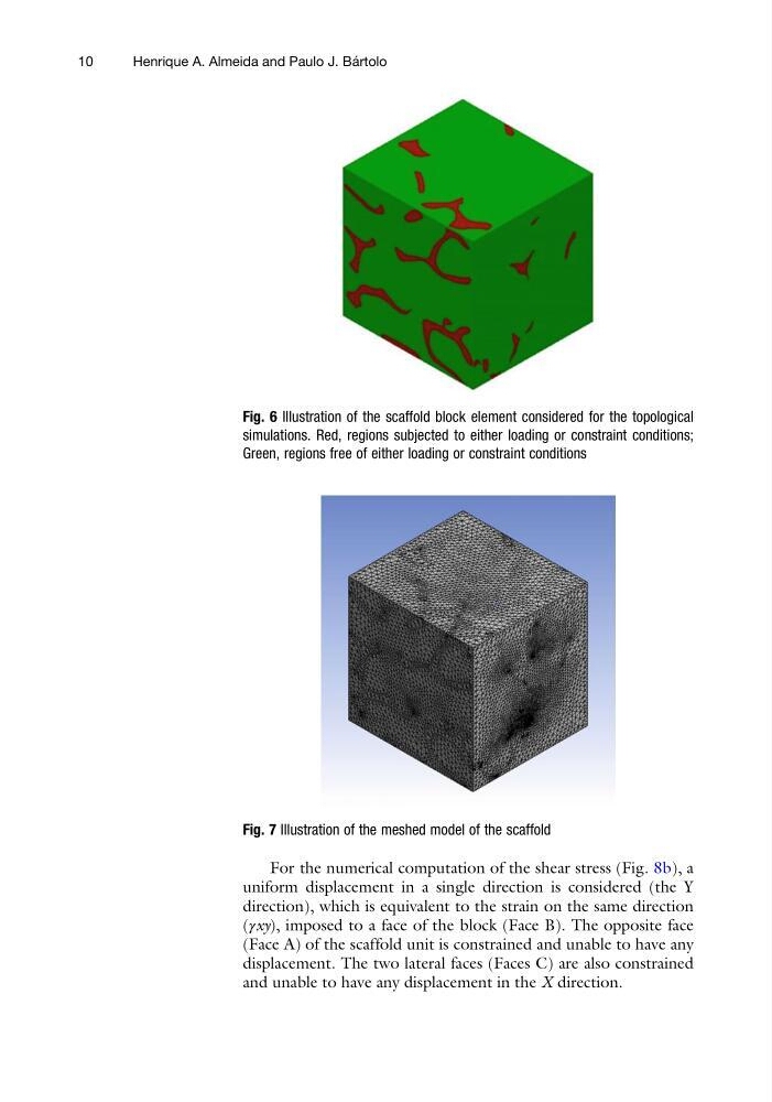
Fig. 6 Illustration of the scaffold block element considered for the topological
simulations. Red, regions subjected to either loading or constraint conditions;
Green, regions free of either loading or constraint conditions
Fig. 7 Illustration of the meshed model of the scaffold
10
Henrique A. Almeida and Paulo J. Ba ´ rtolo
uniform displacement in a single direction is considered (the Y
direction), which is equivalent to the strain on the same direction
(γxy), imposed to a face of the block (Face B). The opposite face
(Face A) of the scaffold unit is constrained and unable to have any
displacement. The two lateral faces (Faces C) are also constrained
and unable to have any displacement in the X direction.
Fig. 6 Illustration of the scaffold block element considered for the topological
simulations. Red, regions subjected to either loading or constraint conditions;
Green, regions free of either loading or constraint conditions
Fig. 7 Illustration of the meshed model of the scaffold
10
Henrique A. Almeida and Paulo J. Ba ´ rtolo