

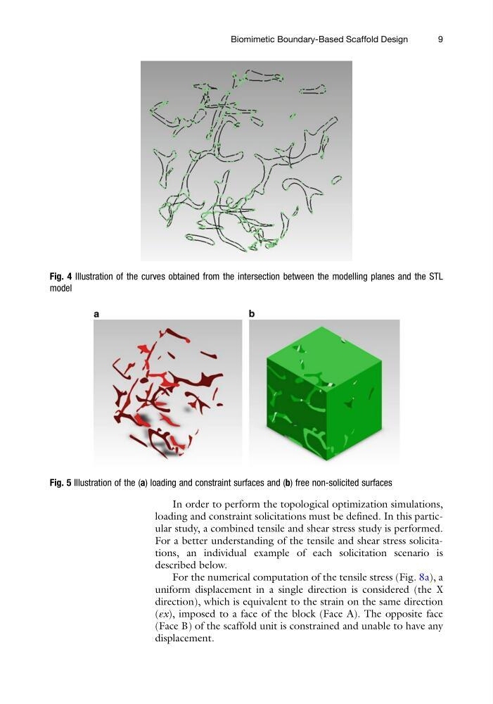
In order to perform the topological optimization simulations,
loading and constraint solicitations must be defined. In this particular study, a combined tensile and shear stress study is performed.
For a better understanding of the tensile and shear stress solicitations, an individual example of each solicitation scenario is
described below.
For the numerical computation of the tensile stress (Fig. 8a), a
uniform displacement in a single direction is considered (the X
direction), which is equivalent to the strain on the same direction
(εx), imposed to a face of the block (Face A). The opposite face
(Face B) of the scaffold unit is constrained and unable to have any
displacement.
Fig. 4 Illustration of the curves obtained from the intersection between the modelling planes and the STL
model
Fig. 5 Illustration of the (a) loading and constraint surfaces and (b) free non-solicited surfaces
Biomimetic Boundary-Based Scaffold Design
9
loading and constraint solicitations must be defined. In this particular study, a combined tensile and shear stress study is performed.
For a better understanding of the tensile and shear stress solicitations, an individual example of each solicitation scenario is
described below.
For the numerical computation of the tensile stress (Fig. 8a), a
uniform displacement in a single direction is considered (the X
direction), which is equivalent to the strain on the same direction
(εx), imposed to a face of the block (Face A). The opposite face
(Face B) of the scaffold unit is constrained and unable to have any
displacement.
Fig. 4 Illustration of the curves obtained from the intersection between the modelling planes and the STL
model
Fig. 5 Illustration of the (a) loading and constraint surfaces and (b) free non-solicited surfaces
Biomimetic Boundary-Based Scaffold Design
9