

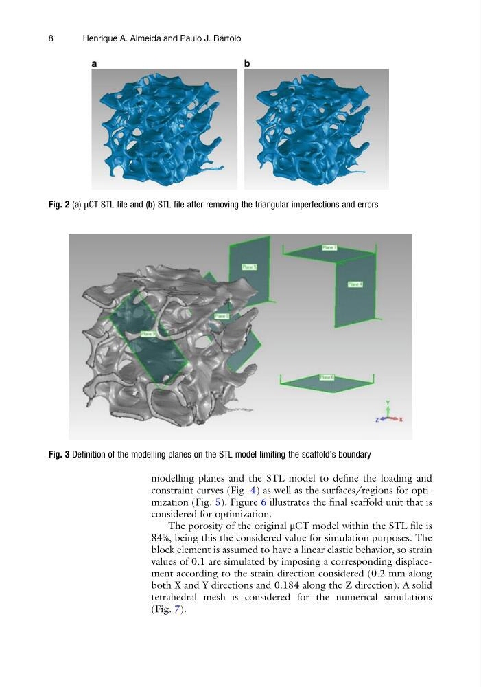
modelling planes and the STL model to define the loading and
constraint curves (Fig. 4) as well as the surfaces/regions for optimization (Fig. 5). Figure 6 illustrates the final scaffold unit that is
considered for optimization.
The porosity of the original μCT model within the STL file is
84%, being this the considered value for simulation purposes. The
block element is assumed to have a linear elastic behavior, so strain
values of 0.1 are simulated by imposing a corresponding displacement according to the strain direction considered (0.2 mm along
both X and Y directions and 0.184 along the Z direction). A solid
tetrahedral mesh is considered for the numerical simulations
(Fig. 7).
Fig. 2 (a) μCT STL file and (b) STL file after removing the triangular imperfections and errors
Fig. 3 Definition of the modelling planes on the STL model limiting the scaffold’s boundary
8
Henrique A. Almeida and Paulo J. Ba ´ rtolo
constraint curves (Fig. 4) as well as the surfaces/regions for optimization (Fig. 5). Figure 6 illustrates the final scaffold unit that is
considered for optimization.
The porosity of the original μCT model within the STL file is
84%, being this the considered value for simulation purposes. The
block element is assumed to have a linear elastic behavior, so strain
values of 0.1 are simulated by imposing a corresponding displacement according to the strain direction considered (0.2 mm along
both X and Y directions and 0.184 along the Z direction). A solid
tetrahedral mesh is considered for the numerical simulations
(Fig. 7).
Fig. 2 (a) μCT STL file and (b) STL file after removing the triangular imperfections and errors
Fig. 3 Definition of the modelling planes on the STL model limiting the scaffold’s boundary
8
Henrique A. Almeida and Paulo J. Ba ´ rtolo