

i
ð Þ
ð
Ω
X 3
i, j , k, l¼1
e
E ijkl η x
ð Þ
ð
Þε ij u x
ð Þ
ð
Þε kl v x
ð Þ
ð
Þdx ¼ l ν
ð Þ
8ν∈U
ii
ð Þ
0 η x
ð Þ 1
8x∈Ω
iii
ð Þ
ð
Ω
η x
ð Þdx Vol
2.1.1 Finite Element
Discretization
for the Optimization
Problem
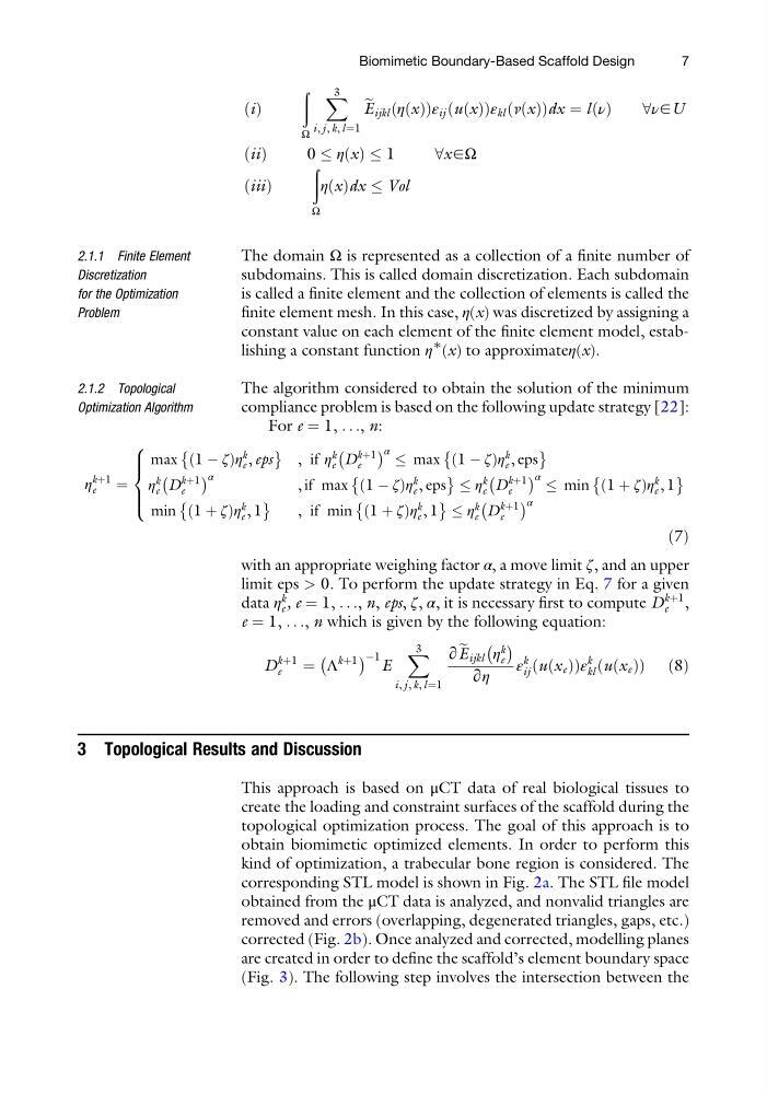
The domain Ω is represented as a collection of a finite number of
subdomains. This is called domain discretization. Each subdomain
is called a finite element and the collection of elements is called the
finite element mesh. In this case, η(x) was discretized by assigning a
constant value on each element of the finite element model, establishing a constant function η
∗
(x) to approximateη(x).
2.1.2 Topological
Optimization Algorithm
The algorithm considered to obtain the solution of the minimum
compliance problem is based on the following update strategy [22]:
For e ¼ 1, . . ., n:
η
kþ1
e
¼
max 1 À ζ
ð
Þη
k
e , eps
È
É
, if η
k
e D
kþ1
e
À
Á α
max 1 À ζ
ð
Þη
k
e , eps
È
É
η
k
e D
kþ1
e
À
Á α
, if max 1 À ζ
ð
Þη
k
e , eps
È
É η
k
e D
kþ1
e
À
Á α
min 1 þ ζ
ð
Þη
k
e , 1
È
É
min 1 þ ζ
ð
Þη
k
e , 1
È
É
, if min 1 þ ζ
ð
Þη
k
e , 1
È
É η
k
e D
kþ1
e
À
Á α
8
> > <
> > :
ð7Þ
with an appropriate weighing factor α, a move limit ζ, and an upper
limit eps > 0. To perform the update strategy in Eq. 7 for a given
data η
k
e , e ¼ 1, . . ., n, eps, ζ, α, it is necessary first to compute D
kþ1
e ,
e ¼ 1, . . ., n which is given by the following equation:
D
kþ1
e
¼ Λ
kþ1
À
Á À1 E
X 3
i, j , k, l¼1
∂ e
E ijkl η
k
e
À Á
∂η
ε
k
ij u x e
ð Þ
ð
Þε
k
kl u x e
ð Þ
ð
Þ ð8Þ
3 Topological Results and Discussion
This approach is based on μCT data of real biological tissues to
create the loading and constraint surfaces of the scaffold during the
topological optimization process. The goal of this approach is to
obtain biomimetic optimized elements. In order to perform this
kind of optimization, a trabecular bone region is considered. The
corresponding STL model is shown in Fig. 2a. The STL file model
obtained from the μCT data is analyzed, and nonvalid triangles are
removed and errors (overlapping, degenerated triangles, gaps, etc.)
corrected (Fig. 2b). Once analyzed and corrected, modelling planes
are created in order to define the scaffold’s element boundary space
(Fig. 3). The following step involves the intersection between the
Biomimetic Boundary-Based Scaffold Design
7
ð Þ
ð
Ω
X 3
i, j , k, l¼1
e
E ijkl η x
ð Þ
ð
Þε ij u x
ð Þ
ð
Þε kl v x
ð Þ
ð
Þdx ¼ l ν
ð Þ
8ν∈U
ii
ð Þ
0 η x
ð Þ 1
8x∈Ω
iii
ð Þ
ð
Ω
η x
ð Þdx Vol
2.1.1 Finite Element
Discretization
for the Optimization
Problem
The domain Ω is represented as a collection of a finite number of
subdomains. This is called domain discretization. Each subdomain
is called a finite element and the collection of elements is called the
finite element mesh. In this case, η(x) was discretized by assigning a
constant value on each element of the finite element model, establishing a constant function η
∗
(x) to approximateη(x).
2.1.2 Topological
Optimization Algorithm
The algorithm considered to obtain the solution of the minimum
compliance problem is based on the following update strategy [22]:
For e ¼ 1, . . ., n:
η
kþ1
e
¼
max 1 À ζ
ð
Þη
k
e , eps
È
É
, if η
k
e D
kþ1
e
À
Á α
max 1 À ζ
ð
Þη
k
e , eps
È
É
η
k
e D
kþ1
e
À
Á α
, if max 1 À ζ
ð
Þη
k
e , eps
È
É η
k
e D
kþ1
e
À
Á α
min 1 þ ζ
ð
Þη
k
e , 1
È
É
min 1 þ ζ
ð
Þη
k
e , 1
È
É
, if min 1 þ ζ
ð
Þη
k
e , 1
È
É η
k
e D
kþ1
e
À
Á α
8
> > <
> > :
ð7Þ
with an appropriate weighing factor α, a move limit ζ, and an upper
limit eps > 0. To perform the update strategy in Eq. 7 for a given
data η
k
e , e ¼ 1, . . ., n, eps, ζ, α, it is necessary first to compute D
kþ1
e ,
e ¼ 1, . . ., n which is given by the following equation:
D
kþ1
e
¼ Λ
kþ1
À
Á À1 E
X 3
i, j , k, l¼1
∂ e
E ijkl η
k
e
À Á
∂η
ε
k
ij u x e
ð Þ
ð
Þε
k
kl u x e
ð Þ
ð
Þ ð8Þ
3 Topological Results and Discussion
This approach is based on μCT data of real biological tissues to
create the loading and constraint surfaces of the scaffold during the
topological optimization process. The goal of this approach is to
obtain biomimetic optimized elements. In order to perform this
kind of optimization, a trabecular bone region is considered. The
corresponding STL model is shown in Fig. 2a. The STL file model
obtained from the μCT data is analyzed, and nonvalid triangles are
removed and errors (overlapping, degenerated triangles, gaps, etc.)
corrected (Fig. 2b). Once analyzed and corrected, modelling planes
are created in order to define the scaffold’s element boundary space
(Fig. 3). The following step involves the intersection between the
Biomimetic Boundary-Based Scaffold Design
7