

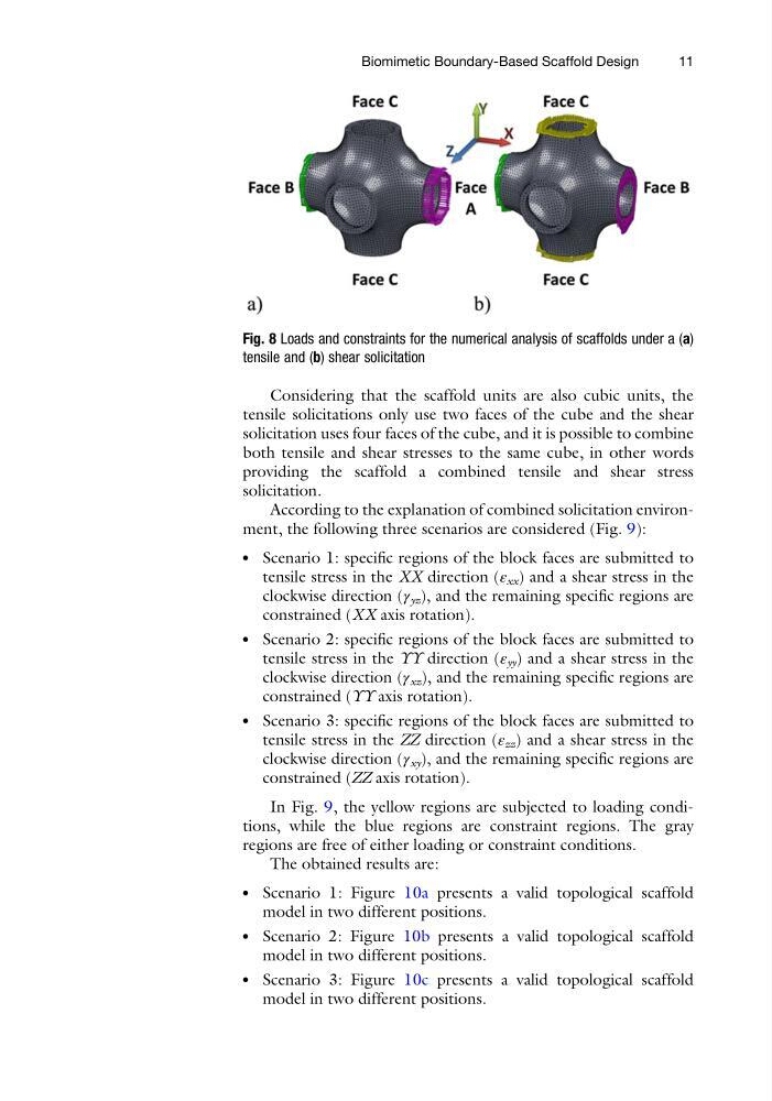
Considering that the scaffold units are also cubic units, the
tensile solicitations only use two faces of the cube and the shear
solicitation uses four faces of the cube, and it is possible to combine
both tensile and shear stresses to the same cube, in other words
providing the scaffold a combined tensile and shear stress
solicitation.
According to the explanation of combined solicitation environment, the following three scenarios are considered (Fig. 9):
l
Scenario 1: specific regions of the block faces are submitted to
tensile stress in the XX direction (ε xx ) and a shear stress in the
clockwise direction (γ yz ), and the remaining specific regions are
constrained (XX axis rotation).
l
Scenario 2: specific regions of the block faces are submitted to
tensile stress in the YY direction (ε yy ) and a shear stress in the
clockwise direction (γ xz ), and the remaining specific regions are
constrained (YY axis rotation).
l
Scenario 3: specific regions of the block faces are submitted to
tensile stress in the ZZ direction (ε zz ) and a shear stress in the
clockwise direction (γ xy ), and the remaining specific regions are
constrained (ZZ axis rotation).
In Fig. 9, the yellow regions are subjected to loading conditions, while the blue regions are constraint regions. The gray
regions are free of either loading or constraint conditions.
The obtained results are:
l
Scenario 1: Figure 10a presents a valid topological scaffold
model in two different positions.
l
Scenario 2: Figure 10b presents a valid topological scaffold
model in two different positions.
l
Scenario 3: Figure 10c presents a valid topological scaffold
model in two different positions.
Fig. 8 Loads and constraints for the numerical analysis of scaffolds under a (a)
tensile and (b) shear solicitation
Biomimetic Boundary-Based Scaffold Design
11
tensile solicitations only use two faces of the cube and the shear
solicitation uses four faces of the cube, and it is possible to combine
both tensile and shear stresses to the same cube, in other words
providing the scaffold a combined tensile and shear stress
solicitation.
According to the explanation of combined solicitation environment, the following three scenarios are considered (Fig. 9):
l
Scenario 1: specific regions of the block faces are submitted to
tensile stress in the XX direction (ε xx ) and a shear stress in the
clockwise direction (γ yz ), and the remaining specific regions are
constrained (XX axis rotation).
l
Scenario 2: specific regions of the block faces are submitted to
tensile stress in the YY direction (ε yy ) and a shear stress in the
clockwise direction (γ xz ), and the remaining specific regions are
constrained (YY axis rotation).
l
Scenario 3: specific regions of the block faces are submitted to
tensile stress in the ZZ direction (ε zz ) and a shear stress in the
clockwise direction (γ xy ), and the remaining specific regions are
constrained (ZZ axis rotation).
In Fig. 9, the yellow regions are subjected to loading conditions, while the blue regions are constraint regions. The gray
regions are free of either loading or constraint conditions.
The obtained results are:
l
Scenario 1: Figure 10a presents a valid topological scaffold
model in two different positions.
l
Scenario 2: Figure 10b presents a valid topological scaffold
model in two different positions.
l
Scenario 3: Figure 10c presents a valid topological scaffold
model in two different positions.
Fig. 8 Loads and constraints for the numerical analysis of scaffolds under a (a)
tensile and (b) shear solicitation
Biomimetic Boundary-Based Scaffold Design
11