

10. Tighten the screws during the assembly of the extrusion heads
to avoid polymer leakages, but not too strongly in order to
avoid mechanical damage.
11. When setting the origin of the vertical axis, move the print
head slowly to avoid crashing the needle against the printing
stage.
12. Getting the desired scaffold morphology is the result of a
balance between temperature, extrusion driving forces (rollers
speed, pressure, and the combination of pressure/screw speed
for FDM, 3DF, and bioextrusion, respectively), and deposition
speed. These parameters are material and machine dependent.
The right parameters to obtain the desired morphology need
to be determined experimentally through a feedback loop of
fabrication and microscopy analysis. In Fig. 14, it is possible to
see the parts fabricated with the set of parameters that led to
fiber thicknesses as close as possible to the nozzle internal
diameters, as later confirmed by SEM analysis.
13. The higher the temperature and the driving forces, the higher
the flow rate. This means that more material is deposited per
length, practically resulting in thicker fibers and sagging. As a
result, the lateral porosity may be compromised. To avoid this
scenario, the deposition speed should be increased accordingly.
Examples of properly printed scaffolds and their average fiber
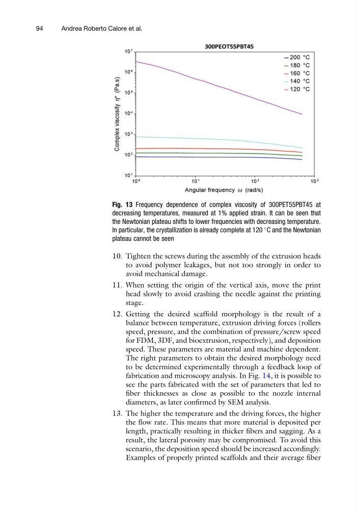
Fig. 13 Frequency dependence of complex viscosity of 300PET55PBT45 at
decreasing temperatures, measured at 1% applied strain. It can be seen that
the Newtonian plateau shifts to lower frequencies with decreasing temperature.
In particular, the crystallization is already complete at 120
C and the Newtonian
plateau cannot be seen
94
Andrea Roberto Calore et al.
to avoid polymer leakages, but not too strongly in order to
avoid mechanical damage.
11. When setting the origin of the vertical axis, move the print
head slowly to avoid crashing the needle against the printing
stage.
12. Getting the desired scaffold morphology is the result of a
balance between temperature, extrusion driving forces (rollers
speed, pressure, and the combination of pressure/screw speed
for FDM, 3DF, and bioextrusion, respectively), and deposition
speed. These parameters are material and machine dependent.
The right parameters to obtain the desired morphology need
to be determined experimentally through a feedback loop of
fabrication and microscopy analysis. In Fig. 14, it is possible to
see the parts fabricated with the set of parameters that led to
fiber thicknesses as close as possible to the nozzle internal
diameters, as later confirmed by SEM analysis.
13. The higher the temperature and the driving forces, the higher
the flow rate. This means that more material is deposited per
length, practically resulting in thicker fibers and sagging. As a
result, the lateral porosity may be compromised. To avoid this
scenario, the deposition speed should be increased accordingly.
Examples of properly printed scaffolds and their average fiber
Fig. 13 Frequency dependence of complex viscosity of 300PET55PBT45 at
decreasing temperatures, measured at 1% applied strain. It can be seen that
the Newtonian plateau shifts to lower frequencies with decreasing temperature.
In particular, the crystallization is already complete at 120
C and the Newtonian
plateau cannot be seen
94
Andrea Roberto Calore et al.