

184
Yu. Kotsiuba et al.
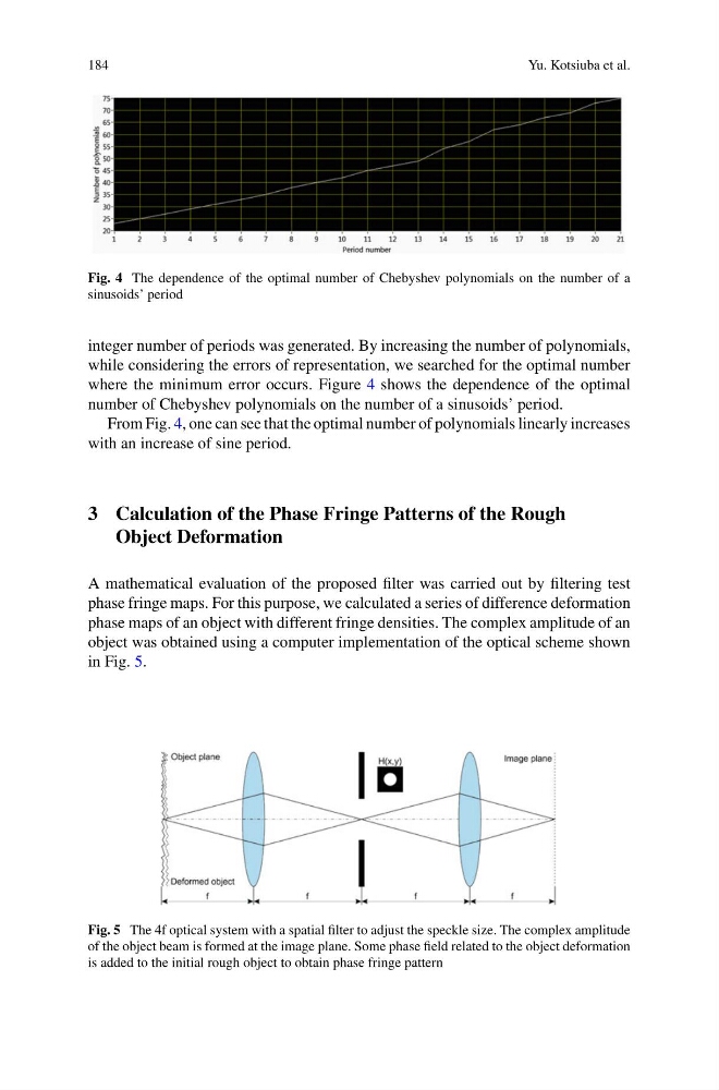
Fig. 4 The dependence of the optimal number of Chebyshev polynomials on the number of a
sinusoids’ period
integer number of periods was generated. By increasing the number of polynomials,
while considering the errors of representation, we searched for the optimal number
where the minimum error occurs. Figure 4 shows the dependence of the optimal
number of Chebyshev polynomials on the number of a sinusoids’ period.
From Fig. 4, one can see that the optimal number of polynomials linearly increases
with an increase of sine period.
3 Calculation of the Phase Fringe Patterns of the Rough
Object Deformation
A mathematical evaluation of the proposed filter was carried out by filtering test
phase fringe maps. For this purpose, we calculated a series of difference deformation
phase maps of an object with different fringe densities. The complex amplitude of an
object was obtained using a computer implementation of the optical scheme shown
in Fig. 5.
Fig. 5 The 4f optical system with a spatial filter to adjust the speckle size. The complex amplitude
of the object beam is formed at the image plane. Some phase field related to the object deformation
is added to the initial rough object to obtain phase fringe pattern
Yu. Kotsiuba et al.
Fig. 4 The dependence of the optimal number of Chebyshev polynomials on the number of a
sinusoids’ period
integer number of periods was generated. By increasing the number of polynomials,
while considering the errors of representation, we searched for the optimal number
where the minimum error occurs. Figure 4 shows the dependence of the optimal
number of Chebyshev polynomials on the number of a sinusoids’ period.
From Fig. 4, one can see that the optimal number of polynomials linearly increases
with an increase of sine period.
3 Calculation of the Phase Fringe Patterns of the Rough
Object Deformation
A mathematical evaluation of the proposed filter was carried out by filtering test
phase fringe maps. For this purpose, we calculated a series of difference deformation
phase maps of an object with different fringe densities. The complex amplitude of an
object was obtained using a computer implementation of the optical scheme shown
in Fig. 5.
Fig. 5 The 4f optical system with a spatial filter to adjust the speckle size. The complex amplitude
of the object beam is formed at the image plane. Some phase field related to the object deformation
is added to the initial rough object to obtain phase fringe pattern