

80
V. L. Borblik
However, explicit dependence of the depletion widths for both sides of the p-n junction on its radius has been not established. Partially, this has been made in paper [8]
but only for the depletion width of the core which (likely to the case of semi-limited
structures [1–3]) increases with decrease in the radius of metallurgical boundary of
the p-n junction. Behavior of the depletion width of the nanowire shell as well as of
the whole depletion width remained not studied.
In experiment, in order to enhance a performance of such devices, p- and n-layers
are made often of different materials that allow enlargement of the built-in electric
field. The radial core–shell solar cells and photodetectors have been fabricated using
the hetero p-n junctions such as Ge/CdS [9], CdS/Cu 2 S [10], ZnO/CuS [11], Si/CdS
[12], GaAs/InGaAs [13], Si/ZnO [14], and others.
At the same time, the radial nanowire structures use often not p-n but p-i-n junctions [15–19]. In particular, this makes it possible to broaden the region of strong
electric field in the junction that is additional advantageous in materials with the
short minority carrier diffusion lengths [20].
In this paper, electrostatics of all such radial structures is analyzed theoretically.
2 Nanowire Radial p-n Junction
2.1 Theory
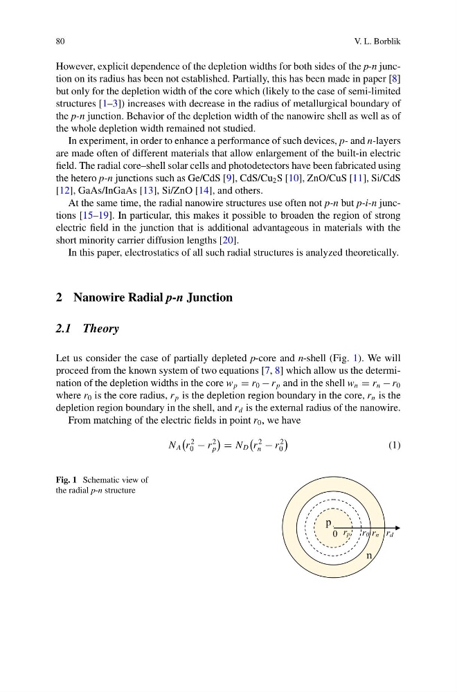
Let us consider the case of partially depleted p-core and n-shell (Fig. 1). We will
proceed from the known system of two equations [7, 8] which allow us the determination of the depletion widths in the core w p = r 0 − r p and in the shell w n = r n − r 0
where r 0 is the core radius, r p is the depletion region boundary in the core, r n is the
depletion region boundary in the shell, and r d is the external radius of the nanowire.
From matching of the electric fields in point r 0 , we have
N A
r
2
0 − r
2
p
= N D
r
2
n − r
2
0
(1)
Fig. 1 Schematic view of
the radial p-n structure
0
r n r d
p
n
r p r 0
V. L. Borblik
However, explicit dependence of the depletion widths for both sides of the p-n junction on its radius has been not established. Partially, this has been made in paper [8]
but only for the depletion width of the core which (likely to the case of semi-limited
structures [1–3]) increases with decrease in the radius of metallurgical boundary of
the p-n junction. Behavior of the depletion width of the nanowire shell as well as of
the whole depletion width remained not studied.
In experiment, in order to enhance a performance of such devices, p- and n-layers
are made often of different materials that allow enlargement of the built-in electric
field. The radial core–shell solar cells and photodetectors have been fabricated using
the hetero p-n junctions such as Ge/CdS [9], CdS/Cu 2 S [10], ZnO/CuS [11], Si/CdS
[12], GaAs/InGaAs [13], Si/ZnO [14], and others.
At the same time, the radial nanowire structures use often not p-n but p-i-n junctions [15–19]. In particular, this makes it possible to broaden the region of strong
electric field in the junction that is additional advantageous in materials with the
short minority carrier diffusion lengths [20].
In this paper, electrostatics of all such radial structures is analyzed theoretically.
2 Nanowire Radial p-n Junction
2.1 Theory
Let us consider the case of partially depleted p-core and n-shell (Fig. 1). We will
proceed from the known system of two equations [7, 8] which allow us the determination of the depletion widths in the core w p = r 0 − r p and in the shell w n = r n − r 0
where r 0 is the core radius, r p is the depletion region boundary in the core, r n is the
depletion region boundary in the shell, and r d is the external radius of the nanowire.
From matching of the electric fields in point r 0 , we have
N A
r
2
0 − r
2
p
= N D
r
2
n − r
2
0
(1)
Fig. 1 Schematic view of
the radial p-n structure
0
r n r d
p
n
r p r 0