

174
V. Malyshev et al.
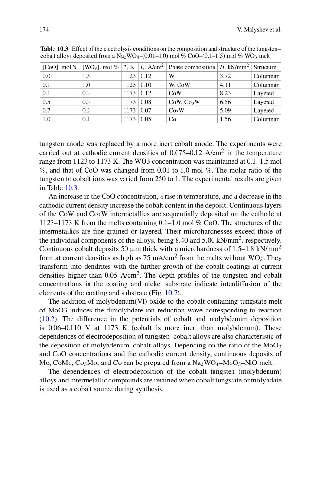
Table 10.3 Effect of the electrolysis conditions on the composition and structure of the tungsten–
cobalt alloys deposited from a Na 2 WO 4 –(0.01–1.0) mol % CoO–(0.1–1.5) mol % WO 3 melt
[CoO], mol % [WO 3 ], mol % T, K i c , A/cm 2 Phase composition H, kN/mm 2 Structure
0.01
1.5
1123 0.12
W
3.72
Columnar
0.1
1.0
1123 0.10
W, CoW
4.11
Columnar
0.1
0.3
1173 0.12
CoW
8.23
Layered
0.5
0.3
1173 0.08
CoW, Co 3 W
6.56
Layered
0.7
0.2
1173 0.07
Co 3 W
5.09
Layered
1.0
0.1
1173 0.05
Co
1.56
Columnar
tungsten anode was replaced by a more inert cobalt anode. The experiments were
carried out at cathodic current densities of 0.075–0.12 A/cm 2 in the temperature
range from 1123 to 1173 K. The WO3 concentration was maintained at 0.1–1.5 mol
%, and that of CoO was changed from 0.01 to 1.0 mol %. The molar ratio of the
tungsten to cobalt ions was varied from 250 to 1. The experimental results are given
in Table 10.3.
An increase in the CoO concentration, a rise in temperature, and a decrease in the
cathodic current density increase the cobalt content in the deposit. Continuous layers
of the CoW and Co 3 W intermetallics are sequentially deposited on the cathode at
1123–1173 K from the melts containing 0.1–1.0 mol % CoO. The structures of the
intermetallics are fine-grained or layered. Their microhardnesses exceed those of
the individual components of the alloys, being 8.40 and 5.00 kN/mm 2 , respectively.
Continuous cobalt deposits 50 μm thick with a microhardness of 1.5–1.8 kN/mm 2
form at current densities as high as 75 mA/cm 2 from the melts without WO 3 . They
transform into dendrites with the further growth of the cobalt coatings at current
densities higher than 0.05 A/cm 2 . The depth profiles of the tungsten and cobalt
concentrations in the coating and nickel substrate indicate interdiffusion of the
elements of the coating and substrate (Fig. 10.7).
The addition of molybdenum(VI) oxide to the cobalt-containing tungstate melt
of MoO3 induces the dimolybdate-ion reduction wave corresponding to reaction
(10.2). The difference in the potentials of cobalt and molybdenum deposition
is 0.06–0.110 V at 1173 K (cobalt is more inert than molybdenum). These
dependences of electrodeposition of tungsten–cobalt alloys are also characteristic of
the deposition of molybdenum–cobalt alloys. Depending on the ratio of the MoO 3
and CoO concentrations and the cathodic current density, continuous deposits of
Mo, CoMo, Co 3 Mo, and Co can be prepared from a Na 2 WO 4 –MoO 3 –NiO melt.
The dependences of electrodeposition of the cobalt–tungsten (molybdenum)
alloys and intermetallic compounds are retained when cobalt tungstate or molybdate
is used as a cobalt source during synthesis.
V. Malyshev et al.
Table 10.3 Effect of the electrolysis conditions on the composition and structure of the tungsten–
cobalt alloys deposited from a Na 2 WO 4 –(0.01–1.0) mol % CoO–(0.1–1.5) mol % WO 3 melt
[CoO], mol % [WO 3 ], mol % T, K i c , A/cm 2 Phase composition H, kN/mm 2 Structure
0.01
1.5
1123 0.12
W
3.72
Columnar
0.1
1.0
1123 0.10
W, CoW
4.11
Columnar
0.1
0.3
1173 0.12
CoW
8.23
Layered
0.5
0.3
1173 0.08
CoW, Co 3 W
6.56
Layered
0.7
0.2
1173 0.07
Co 3 W
5.09
Layered
1.0
0.1
1173 0.05
Co
1.56
Columnar
tungsten anode was replaced by a more inert cobalt anode. The experiments were
carried out at cathodic current densities of 0.075–0.12 A/cm 2 in the temperature
range from 1123 to 1173 K. The WO3 concentration was maintained at 0.1–1.5 mol
%, and that of CoO was changed from 0.01 to 1.0 mol %. The molar ratio of the
tungsten to cobalt ions was varied from 250 to 1. The experimental results are given
in Table 10.3.
An increase in the CoO concentration, a rise in temperature, and a decrease in the
cathodic current density increase the cobalt content in the deposit. Continuous layers
of the CoW and Co 3 W intermetallics are sequentially deposited on the cathode at
1123–1173 K from the melts containing 0.1–1.0 mol % CoO. The structures of the
intermetallics are fine-grained or layered. Their microhardnesses exceed those of
the individual components of the alloys, being 8.40 and 5.00 kN/mm 2 , respectively.
Continuous cobalt deposits 50 μm thick with a microhardness of 1.5–1.8 kN/mm 2
form at current densities as high as 75 mA/cm 2 from the melts without WO 3 . They
transform into dendrites with the further growth of the cobalt coatings at current
densities higher than 0.05 A/cm 2 . The depth profiles of the tungsten and cobalt
concentrations in the coating and nickel substrate indicate interdiffusion of the
elements of the coating and substrate (Fig. 10.7).
The addition of molybdenum(VI) oxide to the cobalt-containing tungstate melt
of MoO3 induces the dimolybdate-ion reduction wave corresponding to reaction
(10.2). The difference in the potentials of cobalt and molybdenum deposition
is 0.06–0.110 V at 1173 K (cobalt is more inert than molybdenum). These
dependences of electrodeposition of tungsten–cobalt alloys are also characteristic of
the deposition of molybdenum–cobalt alloys. Depending on the ratio of the MoO 3
and CoO concentrations and the cathodic current density, continuous deposits of
Mo, CoMo, Co 3 Mo, and Co can be prepared from a Na 2 WO 4 –MoO 3 –NiO melt.
The dependences of electrodeposition of the cobalt–tungsten (molybdenum)
alloys and intermetallic compounds are retained when cobalt tungstate or molybdate
is used as a cobalt source during synthesis.