

10 High-Temperature Electrochemical Synthesis of Nanostructured Coatings. . .
173
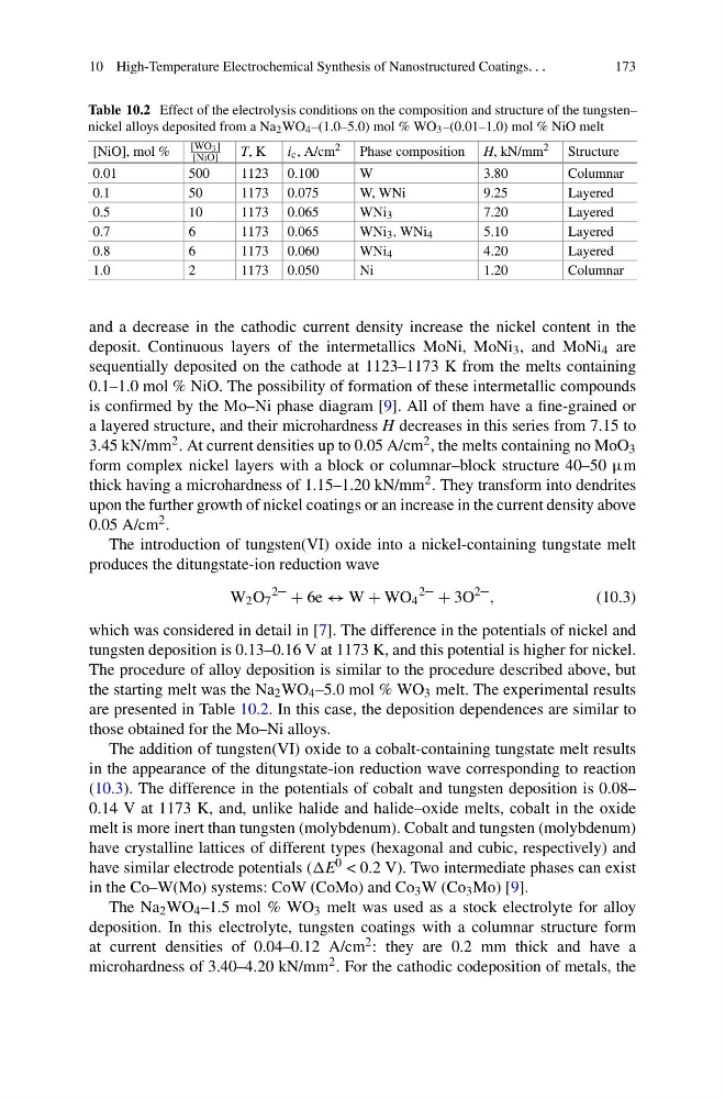
Table 10.2 Effect of the electrolysis conditions on the composition and structure of the tungsten–
nickel alloys deposited from a Na 2 WO 4 –(1.0–5.0) mol % WO 3 –(0.01–1.0) mol % NiO melt
[NiO], mol %
[WO 3 ]
[NiO]
T, K
i c , A/cm 2 Phase composition H, kN/mm 2 Structure
0.01
500
1123 0.100
W
3.80
Columnar
0.1
50
1173 0.075
W, WNi
9.25
Layered
0.5
10
1173 0.065
WNi 3
7.20
Layered
0.7
6
1173 0.065
WNi 3 , WNi 4
5.10
Layered
0.8
6
1173 0.060
WNi 4
4.20
Layered
1.0
2
1173 0.050
Ni
1.20
Columnar
and a decrease in the cathodic current density increase the nickel content in the
deposit. Continuous layers of the intermetallics MoNi, MoNi 3 , and MoNi 4 are
sequentially deposited on the cathode at 1123–1173 K from the melts containing
0.1–1.0 mol % NiO. The possibility of formation of these intermetallic compounds
is confirmed by the Mo–Ni phase diagram [9]. All of them have a fine-grained or
a layered structure, and their microhardness H decreases in this series from 7.15 to
3.45 kN/mm 2 . At current densities up to 0.05 A/cm 2 , the melts containing no MoO 3
form complex nickel layers with a block or columnar–block structure 40–50 μm
thick having a microhardness of 1.15–1.20 kN/mm 2 . They transform into dendrites
upon the further growth of nickel coatings or an increase in the current density above
0.05 A/cm 2 .
The introduction of tungsten(VI) oxide into a nickel-containing tungstate melt
produces the ditungstate-ion reduction wave
W 2 O 7
2–
+ 6e ↔ W + WO 4
2–
+ 3O
2– ,
(10.3)
which was considered in detail in [7]. The difference in the potentials of nickel and
tungsten deposition is 0.13–0.16 V at 1173 K, and this potential is higher for nickel.
The procedure of alloy deposition is similar to the procedure described above, but
the starting melt was the Na 2 WO 4 –5.0 mol % WO 3 melt. The experimental results
are presented in Table 10.2. In this case, the deposition dependences are similar to
those obtained for the Mo–Ni alloys.
The addition of tungsten(VI) oxide to a cobalt-containing tungstate melt results
in the appearance of the ditungstate-ion reduction wave corresponding to reaction
(10.3). The difference in the potentials of cobalt and tungsten deposition is 0.08–
0.14 V at 1173 K, and, unlike halide and halide–oxide melts, cobalt in the oxide
melt is more inert than tungsten (molybdenum). Cobalt and tungsten (molybdenum)
have crystalline lattices of different types (hexagonal and cubic, respectively) and
have similar electrode potentials (E 0 < 0.2 V). Two intermediate phases can exist
in the Co–W(Mo) systems: CoW (CoMo) and Co 3 W (Co 3 Mo) [9].
The Na 2 WO 4 –1.5 mol % WO 3 melt was used as a stock electrolyte for alloy
deposition. In this electrolyte, tungsten coatings with a columnar structure form
at current densities of 0.04–0.12 A/cm 2 : they are 0.2 mm thick and have a
microhardness of 3.40–4.20 kN/mm 2 . For the cathodic codeposition of metals, the
173
Table 10.2 Effect of the electrolysis conditions on the composition and structure of the tungsten–
nickel alloys deposited from a Na 2 WO 4 –(1.0–5.0) mol % WO 3 –(0.01–1.0) mol % NiO melt
[NiO], mol %
[WO 3 ]
[NiO]
T, K
i c , A/cm 2 Phase composition H, kN/mm 2 Structure
0.01
500
1123 0.100
W
3.80
Columnar
0.1
50
1173 0.075
W, WNi
9.25
Layered
0.5
10
1173 0.065
WNi 3
7.20
Layered
0.7
6
1173 0.065
WNi 3 , WNi 4
5.10
Layered
0.8
6
1173 0.060
WNi 4
4.20
Layered
1.0
2
1173 0.050
Ni
1.20
Columnar
and a decrease in the cathodic current density increase the nickel content in the
deposit. Continuous layers of the intermetallics MoNi, MoNi 3 , and MoNi 4 are
sequentially deposited on the cathode at 1123–1173 K from the melts containing
0.1–1.0 mol % NiO. The possibility of formation of these intermetallic compounds
is confirmed by the Mo–Ni phase diagram [9]. All of them have a fine-grained or
a layered structure, and their microhardness H decreases in this series from 7.15 to
3.45 kN/mm 2 . At current densities up to 0.05 A/cm 2 , the melts containing no MoO 3
form complex nickel layers with a block or columnar–block structure 40–50 μm
thick having a microhardness of 1.15–1.20 kN/mm 2 . They transform into dendrites
upon the further growth of nickel coatings or an increase in the current density above
0.05 A/cm 2 .
The introduction of tungsten(VI) oxide into a nickel-containing tungstate melt
produces the ditungstate-ion reduction wave
W 2 O 7
2–
+ 6e ↔ W + WO 4
2–
+ 3O
2– ,
(10.3)
which was considered in detail in [7]. The difference in the potentials of nickel and
tungsten deposition is 0.13–0.16 V at 1173 K, and this potential is higher for nickel.
The procedure of alloy deposition is similar to the procedure described above, but
the starting melt was the Na 2 WO 4 –5.0 mol % WO 3 melt. The experimental results
are presented in Table 10.2. In this case, the deposition dependences are similar to
those obtained for the Mo–Ni alloys.
The addition of tungsten(VI) oxide to a cobalt-containing tungstate melt results
in the appearance of the ditungstate-ion reduction wave corresponding to reaction
(10.3). The difference in the potentials of cobalt and tungsten deposition is 0.08–
0.14 V at 1173 K, and, unlike halide and halide–oxide melts, cobalt in the oxide
melt is more inert than tungsten (molybdenum). Cobalt and tungsten (molybdenum)
have crystalline lattices of different types (hexagonal and cubic, respectively) and
have similar electrode potentials (E 0 < 0.2 V). Two intermediate phases can exist
in the Co–W(Mo) systems: CoW (CoMo) and Co 3 W (Co 3 Mo) [9].
The Na 2 WO 4 –1.5 mol % WO 3 melt was used as a stock electrolyte for alloy
deposition. In this electrolyte, tungsten coatings with a columnar structure form
at current densities of 0.04–0.12 A/cm 2 : they are 0.2 mm thick and have a
microhardness of 3.40–4.20 kN/mm 2 . For the cathodic codeposition of metals, the