

�
70
Biologically Inspired Robotics
is the finish conditions of the motion.
θ = ⎡ ⎣ θ 1 , , θ n ⎤ ⎦
T
4.3.1.2 Control Method
Generally, a computed torque method with linear feedback compensation
can be adopted to realize trajectory tracking, based on the linearization and
decoupling of a nonlinear and coupled system. However, for a hyper dynamic
manipulator, because of the assumption of utilizing dynamically coupled
driving and the ultra-high-motion speed, the real-time problem of control
becomes more difficult compared to that of conventional manipulators even
when adopting a computed torque method with linear feedback compensation. Therefore, a simplified feedforward system with a proportional-derivative (PD) controller is adopted instead of computed torque method.
4.3.2 Case Study: Motion Generation and Control of a Golf Swing Robot
As a study case, herein we discuss the motion generation and control of the
real golf swing robot shown in Figure 4.4. For simplicity, we assume that the
motion of the golf swing robot is on a plane, called a swing plane, and consider
the motion of the arm and the club only. According to the above assumption,
a simple model of the golf swing robot is used as shown in Figure 4.6.
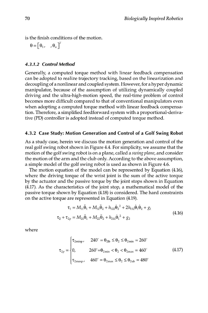
The motion equation of the model can be represented by Equation (4.16),
where the driving torque of the wrist joint is the sum of the active torque
by the actuator and the passive torque by the joint stops shown in Equation
(4.17). As the characteristics of the joint stop, a mathematical model of the
passive torque shown by Equation (4.18) is considered. The hard constraints
on the active torque are represented in Equation (4.19).
τ 1 = M 11 θ qq
qq
q 2
q q
1 + M 12 θ 2 + h 122 θ 2 + 2h 112 θ 1 θ 2 + g 1
(4.16)
τ 2 2 + τ 2p = M qq
21 θ
22 θ qq
2 + h q 2
1 + M
211 θ 1 + g 2
wh ere
⎧ τ
K
2lb ≤ θ
K
⎪
2minp , 240 = θ
2 ≤ θ 2min = 260
⎪
τ =
K
2S
⎨ 0,
260 =θ 2min < θ 2 < θ 2max = 460
K
(4.17)
⎪
⎪τ 2
, 460
K
maxp
= θ
≤ θ ≤ θ = 480
K
⎩
2max
2
2ub
70
Biologically Inspired Robotics
is the finish conditions of the motion.
θ = ⎡ ⎣ θ 1 , , θ n ⎤ ⎦
T
4.3.1.2 Control Method
Generally, a computed torque method with linear feedback compensation
can be adopted to realize trajectory tracking, based on the linearization and
decoupling of a nonlinear and coupled system. However, for a hyper dynamic
manipulator, because of the assumption of utilizing dynamically coupled
driving and the ultra-high-motion speed, the real-time problem of control
becomes more difficult compared to that of conventional manipulators even
when adopting a computed torque method with linear feedback compensation. Therefore, a simplified feedforward system with a proportional-derivative (PD) controller is adopted instead of computed torque method.
4.3.2 Case Study: Motion Generation and Control of a Golf Swing Robot
As a study case, herein we discuss the motion generation and control of the
real golf swing robot shown in Figure 4.4. For simplicity, we assume that the
motion of the golf swing robot is on a plane, called a swing plane, and consider
the motion of the arm and the club only. According to the above assumption,
a simple model of the golf swing robot is used as shown in Figure 4.6.
The motion equation of the model can be represented by Equation (4.16),
where the driving torque of the wrist joint is the sum of the active torque
by the actuator and the passive torque by the joint stops shown in Equation
(4.17). As the characteristics of the joint stop, a mathematical model of the
passive torque shown by Equation (4.18) is considered. The hard constraints
on the active torque are represented in Equation (4.19).
τ 1 = M 11 θ qq
q 2
q q
1 + M 12 θ 2 + h 122 θ 2 + 2h 112 θ 1 θ 2 + g 1
(4.16)
τ 2 2 + τ 2p = M qq
21 θ
22 θ qq
2 + h q 2
1 + M
211 θ 1 + g 2
wh ere
⎧ τ
K
2lb ≤ θ
K
⎪
2minp , 240 = θ
2 ≤ θ 2min = 260
⎪
τ =
K
2S
⎨ 0,
260 =θ 2min < θ 2 < θ 2max = 460
K
(4.17)
⎪
⎪τ 2
, 460
K
maxp
= θ
≤ θ ≤ θ = 480
K
⎩
2max
2
2ub