

39
Analysis and Design of a Bionic Fitness Cycle
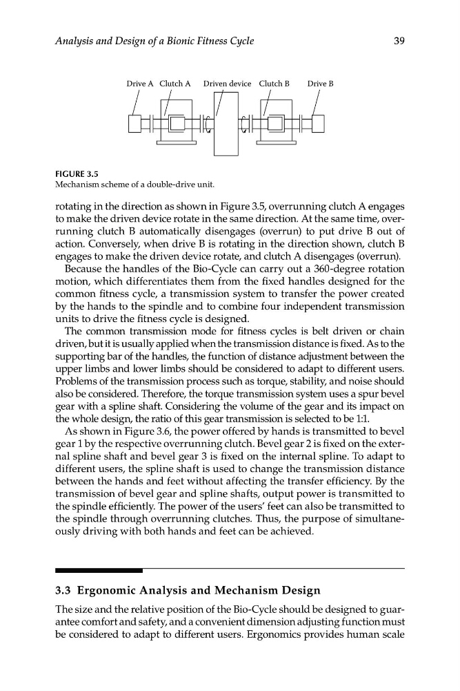
Drive A
Drive B
Clutch A
Clutch B
Driven device
FIGURE 3.5
Mechanism scheme of a double-drive unit.
rotating in the direction as shown in Figure 3.5, overrunning clutch A engages
to make the driven device rotate in the same direction. At the same time, overrunning clutch B automatically disengages (overrun) to put drive B out of
action. Conversely, when drive B is rotating in the direction shown, clutch B
engages to make the driven device rotate, and clutch A disengages (overrun).
Because the handles of the Bio-Cycle can carry out a 360-degree rotation
motion, which differentiates them from the fixed handles designed for the
common fitness cycle, a transmission system to transfer the power created
by the hands to the spindle and to combine four independent transmission
units to drive the fitness cycle is designed.
The common transmission mode for fitness cycles is belt driven or chain
driven, but it is usually applied when the transmission distance is fixed. As to the
supporting bar of the handles, the function of distance adjustment between the
upper limbs and lower limbs should be considered to adapt to different users.
Problems of the transmission process such as torque, stability, and noise should
also be considered. Therefore, the torque transmission system uses a spur bevel
gear with a spline shaft. Considering the volume of the gear and its impact on
the whole design, the ratio of this gear transmission is selected to be 1:1.
As shown in Figure 3.6, the power offered by hands is transmitted to bevel
gear 1 by the respective overrunning clutch. Bevel gear 2 is fixed on the external spline shaft and bevel gear 3 is fixed on the internal spline. To adapt to
different users, the spline shaft is used to change the transmission distance
between the hands and feet without affecting the transfer efficiency. By the
transmission of bevel gear and spline shafts, output power is transmitted to
the spindle efficiently. The power of the users’ feet can also be transmitted to
the spindle through overrunning clutches. Thus, the purpose of simultaneously driving with both hands and feet can be achieved.
3.3 Ergonomic Analysis and Mechanism Design
The size and the relative position of the Bio-Cycle should be designed to guarantee comfort and safety, and a convenient dimension adjusting function must
be considered to adapt to different users. Ergonomics provides human scale
Analysis and Design of a Bionic Fitness Cycle
Drive A
Drive B
Clutch A
Clutch B
Driven device
FIGURE 3.5
Mechanism scheme of a double-drive unit.
rotating in the direction as shown in Figure 3.5, overrunning clutch A engages
to make the driven device rotate in the same direction. At the same time, overrunning clutch B automatically disengages (overrun) to put drive B out of
action. Conversely, when drive B is rotating in the direction shown, clutch B
engages to make the driven device rotate, and clutch A disengages (overrun).
Because the handles of the Bio-Cycle can carry out a 360-degree rotation
motion, which differentiates them from the fixed handles designed for the
common fitness cycle, a transmission system to transfer the power created
by the hands to the spindle and to combine four independent transmission
units to drive the fitness cycle is designed.
The common transmission mode for fitness cycles is belt driven or chain
driven, but it is usually applied when the transmission distance is fixed. As to the
supporting bar of the handles, the function of distance adjustment between the
upper limbs and lower limbs should be considered to adapt to different users.
Problems of the transmission process such as torque, stability, and noise should
also be considered. Therefore, the torque transmission system uses a spur bevel
gear with a spline shaft. Considering the volume of the gear and its impact on
the whole design, the ratio of this gear transmission is selected to be 1:1.
As shown in Figure 3.6, the power offered by hands is transmitted to bevel
gear 1 by the respective overrunning clutch. Bevel gear 2 is fixed on the external spline shaft and bevel gear 3 is fixed on the internal spline. To adapt to
different users, the spline shaft is used to change the transmission distance
between the hands and feet without affecting the transfer efficiency. By the
transmission of bevel gear and spline shafts, output power is transmitted to
the spindle efficiently. The power of the users’ feet can also be transmitted to
the spindle through overrunning clutches. Thus, the purpose of simultaneously driving with both hands and feet can be achieved.
3.3 Ergonomic Analysis and Mechanism Design
The size and the relative position of the Bio-Cycle should be designed to guarantee comfort and safety, and a convenient dimension adjusting function must
be considered to adapt to different users. Ergonomics provides human scale