

255
Multifunctional Actuators for Assistive Knee Braces
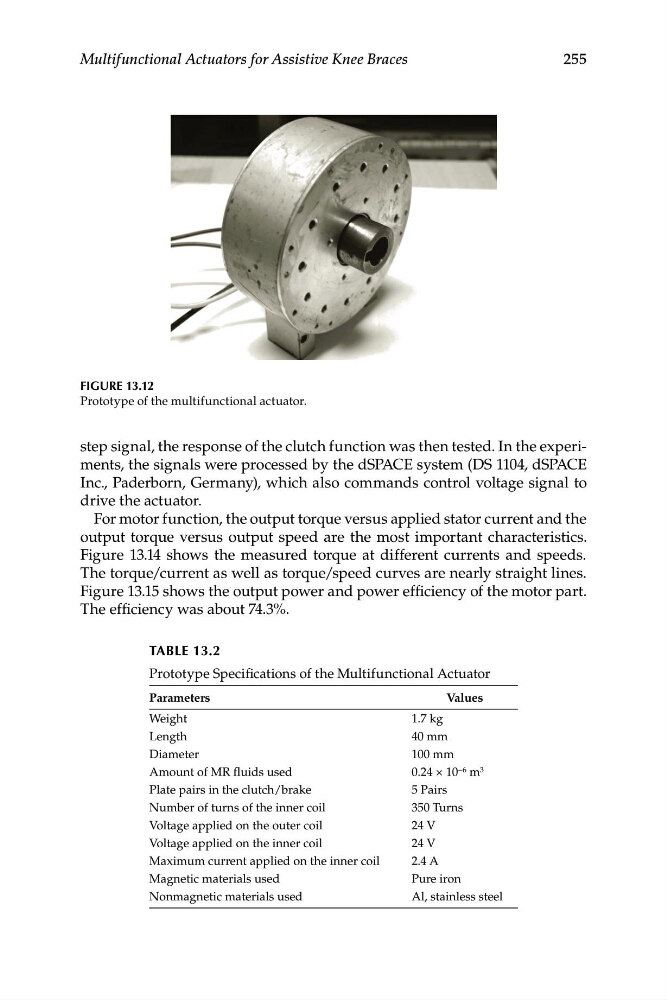
FIGURE 13.12
Prototype of the multifunctional actuator.
step signal, the response of the clutch function was then tested. In the experiments, the signals were processed by the dSPACE system (DS 1104, dSPACE
Inc., Paderborn, Germany), which also commands control voltage signal to
drive the actuator.
For motor function, the output torque versus applied stator current and the
output torque versus output speed are the most important characteristics.
Figure 13.14 shows the measured torque at different currents and speeds.
The torque/current as well as torque/speed curves are nearly straight lines.
Figure 13.15 shows the output power and power efficiency of the motor part.
The efficiency was about 74.3%.
TABLE 13.2
Prototype Specifications of the Multifunctional Actuator
Parameters
Values
Weight
1.7 kg
Length
40 mm
Diameter
100 mm
Amount of MR fluids used
0.24 × 10 −6 m 3
Plate pairs in the clutch/brake
5 Pairs
Number of turns of the inner coil
350 Turns
Voltage applied on the outer coil
24 V
Voltage applied on the inner coil
24 V
Maximum current applied on the inner coil
2.4 A
Magnetic materials used
Pure iron
Nonmagnetic materials used
Al, stainless steel
Multifunctional Actuators for Assistive Knee Braces
FIGURE 13.12
Prototype of the multifunctional actuator.
step signal, the response of the clutch function was then tested. In the experiments, the signals were processed by the dSPACE system (DS 1104, dSPACE
Inc., Paderborn, Germany), which also commands control voltage signal to
drive the actuator.
For motor function, the output torque versus applied stator current and the
output torque versus output speed are the most important characteristics.
Figure 13.14 shows the measured torque at different currents and speeds.
The torque/current as well as torque/speed curves are nearly straight lines.
Figure 13.15 shows the output power and power efficiency of the motor part.
The efficiency was about 74.3%.
TABLE 13.2
Prototype Specifications of the Multifunctional Actuator
Parameters
Values
Weight
1.7 kg
Length
40 mm
Diameter
100 mm
Amount of MR fluids used
0.24 × 10 −6 m 3
Plate pairs in the clutch/brake
5 Pairs
Number of turns of the inner coil
350 Turns
Voltage applied on the outer coil
24 V
Voltage applied on the inner coil
24 V
Maximum current applied on the inner coil
2.4 A
Magnetic materials used
Pure iron
Nonmagnetic materials used
Al, stainless steel