

254
Biologically Inspired Robotics
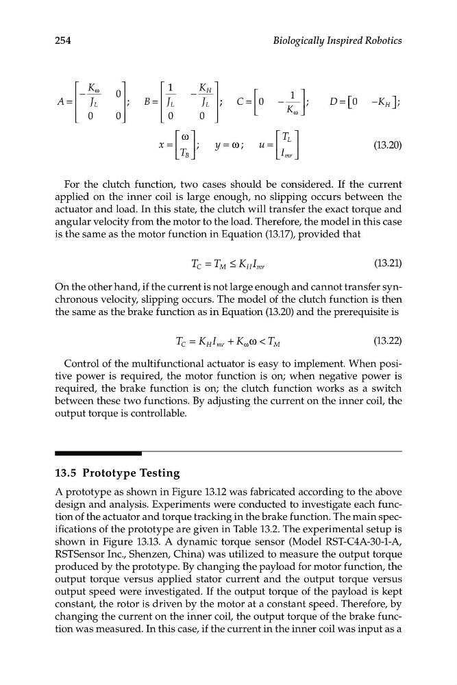
⎡ K
⎤
⎡ 1
−
ω
K H
⎢
0
⎤
⎥
⎢
−
⎥
⎡
1 ⎤
A =
J L
; B = J L
J L
C =
⎢
⎥
⎢ 0 −
⎥ ;
D = ⎡ ⎣ 0 −K
⎢
H ⎤ ⎦
⎥
;
⎣
K ⎦
⎢ 0
0 ⎥
ω
⎣
⎦
⎢ ⎣ 0
0 ⎥ ⎦
⎡ ω ⎤
⎡ T ⎤
x = ⎢ ⎥
y = ω u =
L
⎢ ⎥
(13.20)
⎣ T B ⎦
⎣ I mr ⎦
For the clutch function, two cases should be considered. If the current
applied on the inner coil is large enough, no slipping occurs between the
actuator and load. In this state, the clutch will transfer the exact torque and
angular velocity from the motor to the load. Therefore, the model in this case
is the same as the motor function in Equation (13.17), provided that
T C = T M ≤ K H I m r
(1 3.21)
On the other hand, if the current is not large enough and cannot transfer synchronous velocity, slipping occurs. The model of the clutch function is then
the same as the brake function as in Equation (13.20) and the prerequisite is
T C = K H I +
m r
K ω ω < T M
(1 3.22)
Control of the multifunctional actuator is easy to implement. When positive power is required, the motor function is on; when negative power is
required, the brake function is on; the clutch function works as a switch
between these two functions. By adjusting the current on the inner coil, the
output torque is controllable.
13.5 Prototype Testing
A prototype as shown in Figure 13.12 was fabricated according to the above
design and analysis. Experiments were conducted to investigate each function of the actuator and torque tracking in the brake function. The main specifications of the prototype are given in Table 13.2. The experimental setup is
shown in Figure 13.13. A dynamic torque sensor (Model RST-C4A-30-1-A,
RSTSensor Inc., Shenzen, China) was utilized to measure the output torque
produced by the prototype. By changing the payload for motor function, the
output torque versus applied stator current and the output torque versus
output speed were investigated. If the output torque of the payload is kept
constant, the rotor is driven by the motor at a constant speed. Therefore, by
changing the current on the inner coil, the output torque of the brake function was measured. In this case, if the current in the inner coil was input as a
; ;
Biologically Inspired Robotics
⎡ K
⎤
⎡ 1
−
ω
K H
⎢
0
⎤
⎥
⎢
−
⎥
⎡
1 ⎤
A =
J L
; B = J L
J L
C =
⎢
⎥
⎢ 0 −
⎥ ;
D = ⎡ ⎣ 0 −K
⎢
H ⎤ ⎦
⎥
;
⎣
K ⎦
⎢ 0
0 ⎥
ω
⎣
⎦
⎢ ⎣ 0
0 ⎥ ⎦
⎡ ω ⎤
⎡ T ⎤
x = ⎢ ⎥
y = ω u =
L
⎢ ⎥
(13.20)
⎣ T B ⎦
⎣ I mr ⎦
For the clutch function, two cases should be considered. If the current
applied on the inner coil is large enough, no slipping occurs between the
actuator and load. In this state, the clutch will transfer the exact torque and
angular velocity from the motor to the load. Therefore, the model in this case
is the same as the motor function in Equation (13.17), provided that
T C = T M ≤ K H I m r
(1 3.21)
On the other hand, if the current is not large enough and cannot transfer synchronous velocity, slipping occurs. The model of the clutch function is then
the same as the brake function as in Equation (13.20) and the prerequisite is
T C = K H I +
m r
K ω ω < T M
(1 3.22)
Control of the multifunctional actuator is easy to implement. When positive power is required, the motor function is on; when negative power is
required, the brake function is on; the clutch function works as a switch
between these two functions. By adjusting the current on the inner coil, the
output torque is controllable.
13.5 Prototype Testing
A prototype as shown in Figure 13.12 was fabricated according to the above
design and analysis. Experiments were conducted to investigate each function of the actuator and torque tracking in the brake function. The main specifications of the prototype are given in Table 13.2. The experimental setup is
shown in Figure 13.13. A dynamic torque sensor (Model RST-C4A-30-1-A,
RSTSensor Inc., Shenzen, China) was utilized to measure the output torque
produced by the prototype. By changing the payload for motor function, the
output torque versus applied stator current and the output torque versus
output speed were investigated. If the output torque of the payload is kept
constant, the rotor is driven by the motor at a constant speed. Therefore, by
changing the current on the inner coil, the output torque of the brake function was measured. In this case, if the current in the inner coil was input as a
; ;