

1
ANSYS 11.0
JUN 14 2010
21 : 46 : 13
NODAL SOLUTION
STEP = 2
SUB = 1
TIME = 2
AZ
RSYS = 0
SMX = .463E–04
.772E–06
.232E–05
.386E–05
.695E–05
.849E–05
.100E–04
.131E–04
.147E–04
.178E–04
.193E–04
.208E–04
.239E–04
.255E–04
.270E–04
.301E–04
.316E–04
.347E–04
.363E–04
.378E–04
.409E–04
.424E–04
.455E–04
251
Multifunctional Actuators for Assistive Knee Braces
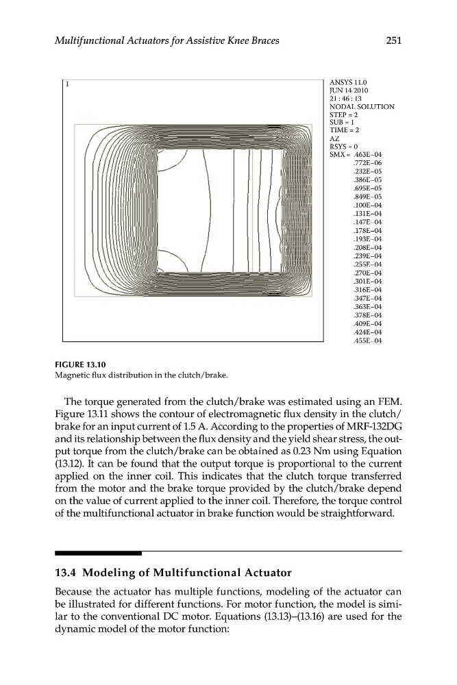
FIGURE 13.10
Magnetic flux distribution in the clutch/brake.
The torque generated from the clutch/brake was estimated using an FEM.
Figure 13.11 shows the contour of electromagnetic flux density in the clutch/
brake for an input current of 1.5 A. According to the properties of MRF-132DG
and its relationship between the flux density and the yield shear stress, the output torque from the clutch/brake can be obtained as 0.23 Nm using Equation
(13.12). It can be found that the output torque is proportional to the current
applied on the inner coil. This indicates that the clutch torque transferred
from the motor and the brake torque provided by the clutch/brake depend
on the value of current applied to the inner coil. Therefore, the torque control
of the multifunctional actuator in brake function would be straightforward.
13.4 Modeling of Multifunctional Actuator
Because the actuator has multiple functions, modeling of the actuator can
be illustrated for different functions. For motor function, the model is similar to the conventional DC motor. Equations (13.13)–(13.16) are used for the
dynamic model of the motor function:
ANSYS 11.0
JUN 14 2010
21 : 46 : 13
NODAL SOLUTION
STEP = 2
SUB = 1
TIME = 2
AZ
RSYS = 0
SMX = .463E–04
.772E–06
.232E–05
.386E–05
.695E–05
.849E–05
.100E–04
.131E–04
.147E–04
.178E–04
.193E–04
.208E–04
.239E–04
.255E–04
.270E–04
.301E–04
.316E–04
.347E–04
.363E–04
.378E–04
.409E–04
.424E–04
.455E–04
251
Multifunctional Actuators for Assistive Knee Braces
FIGURE 13.10
Magnetic flux distribution in the clutch/brake.
The torque generated from the clutch/brake was estimated using an FEM.
Figure 13.11 shows the contour of electromagnetic flux density in the clutch/
brake for an input current of 1.5 A. According to the properties of MRF-132DG
and its relationship between the flux density and the yield shear stress, the output torque from the clutch/brake can be obtained as 0.23 Nm using Equation
(13.12). It can be found that the output torque is proportional to the current
applied on the inner coil. This indicates that the clutch torque transferred
from the motor and the brake torque provided by the clutch/brake depend
on the value of current applied to the inner coil. Therefore, the torque control
of the multifunctional actuator in brake function would be straightforward.
13.4 Modeling of Multifunctional Actuator
Because the actuator has multiple functions, modeling of the actuator can
be illustrated for different functions. For motor function, the model is similar to the conventional DC motor. Equations (13.13)–(13.16) are used for the
dynamic model of the motor function: