

248
Biologically Inspired Robotics
MR fluids
Permanent
magnet
Outer coil
Stator
Spacer
Pin
Clutch/brake
part
Inner coil
Rotor
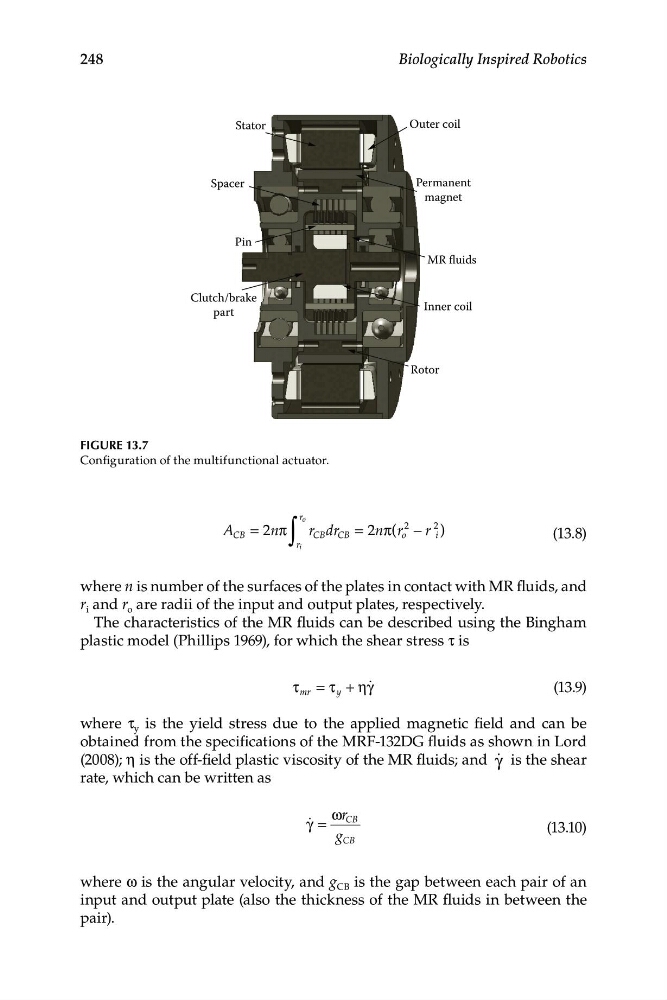
FIGURE 13.7
Configuration of the multifunctional actuator.
A
∫
o
r
CB = 2nπ r CB dr CB = 2n π(r
2
o − r
2
i )
(13.8)
r i
where n is number of the surfaces of the plates in contact with MR fluids, and
r i and r o are radii of the input and output plates, respectively.
The characteristics of the MR fluids can be described using the Bingham
plastic model (Phillips 1969), for which the shear stress τ is
τ mr = τ y + ηγ q
(1 3.9)
where τ y is the yield stress due to the applied magnetic field and can be
obtained from the specifications of the MRF-132DG fluids as shown in Lord
(2008); η is the off-field plastic viscosity of the MR fluids; and γ q is the shear
rate, which can be written as
ωr
γ q =
CB
(13.10)
g CB
where ω is the angular velocity, and g CB is the gap between each pair of an
input and output plate (also the thickness of the MR fluids in between the
pair).
Biologically Inspired Robotics
MR fluids
Permanent
magnet
Outer coil
Stator
Spacer
Pin
Clutch/brake
part
Inner coil
Rotor
FIGURE 13.7
Configuration of the multifunctional actuator.
A
∫
o
r
CB = 2nπ r CB dr CB = 2n π(r
2
o − r
2
i )
(13.8)
r i
where n is number of the surfaces of the plates in contact with MR fluids, and
r i and r o are radii of the input and output plates, respectively.
The characteristics of the MR fluids can be described using the Bingham
plastic model (Phillips 1969), for which the shear stress τ is
τ mr = τ y + ηγ q
(1 3.9)
where τ y is the yield stress due to the applied magnetic field and can be
obtained from the specifications of the MRF-132DG fluids as shown in Lord
(2008); η is the off-field plastic viscosity of the MR fluids; and γ q is the shear
rate, which can be written as
ωr
γ q =
CB
(13.10)
g CB
where ω is the angular velocity, and g CB is the gap between each pair of an
input and output plate (also the thickness of the MR fluids in between the
pair).