

247
Multifunctional Actuators for Assistive Knee Braces
Spacer ring
Shaft
Input plate
Pin
Output plate
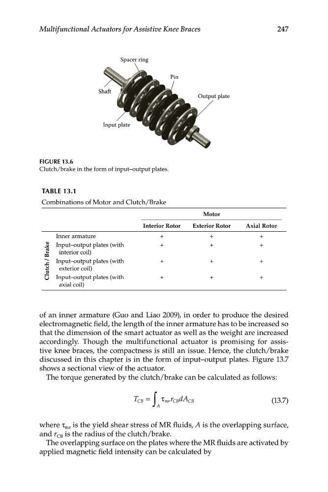
FIGURE 13.6
Clutch/brake in the form of input–output plates.
TABLE 13.1
Combinations of Motor and Clutch/Brake
Interior Rotor
Motor
Exterior Rotor
Axial Rotor
Inner armature
+
+
+
ke
Input–output plates (with
+
+
+
Bra
interior coil)
Input–output plates (with
+
+
+
exterior coil)
Clutch /
Input–output plates (with
+
+
+
axial coil)
of an inner armature (Guo and Liao 2009), in order to produce the desired
electromagnetic field, the length of the inner armature has to be increased so
that the dimension of the smart actuator as well as the weight are increased
accordingly. Though the multifunctional actuator is promising for assistive knee braces, the compactness is still an issue. Hence, the clutch/brake
discussed in this chapter is in the form of input–output plates. Figure 13.7
shows a sectional view of the actuator.
The torque generated by the clutch/brake can be calculated as follows:
T
r d A
CB =
∫
τ mr CB CB
(13.7)
A
where τ mr is the yield shear stress of MR fluids, A is the overlapping surface,
and r CB is the radius of the clutch/brake.
The overlapping surface on the plates where the MR fluids are activated by
applied magnetic field intensity can be calculated by
Multifunctional Actuators for Assistive Knee Braces
Spacer ring
Shaft
Input plate
Pin
Output plate
FIGURE 13.6
Clutch/brake in the form of input–output plates.
TABLE 13.1
Combinations of Motor and Clutch/Brake
Interior Rotor
Motor
Exterior Rotor
Axial Rotor
Inner armature
+
+
+
ke
Input–output plates (with
+
+
+
Bra
interior coil)
Input–output plates (with
+
+
+
exterior coil)
Clutch /
Input–output plates (with
+
+
+
axial coil)
of an inner armature (Guo and Liao 2009), in order to produce the desired
electromagnetic field, the length of the inner armature has to be increased so
that the dimension of the smart actuator as well as the weight are increased
accordingly. Though the multifunctional actuator is promising for assistive knee braces, the compactness is still an issue. Hence, the clutch/brake
discussed in this chapter is in the form of input–output plates. Figure 13.7
shows a sectional view of the actuator.
The torque generated by the clutch/brake can be calculated as follows:
T
r d A
CB =
∫
τ mr CB CB
(13.7)
A
where τ mr is the yield shear stress of MR fluids, A is the overlapping surface,
and r CB is the radius of the clutch/brake.
The overlapping surface on the plates where the MR fluids are activated by
applied magnetic field intensity can be calculated by