

246
Biologically Inspired Robotics
number of pole pairs; and a is the number of parallel paths in the winding.
When the current is larger than this value, the permanent magnet will be
demagnetized and thus impair the performance of the motor part.
In order to design a compact actuator used in assistive knee braces, the hall
sensor commonly used in BLPM DC motors was removed. The indirect rotor
position sensing can be obtained through back electromagnetic field (EMF)
detection in an unexcited phase winding.
13.2.2 Clutch/Brake Design
The clutch/brake is placed inside the motor together with the MR fluids to
produce the torque. Similar to designing the motor, there are several configurations of the clutch/brake. The clutch/brake of the actuator may be
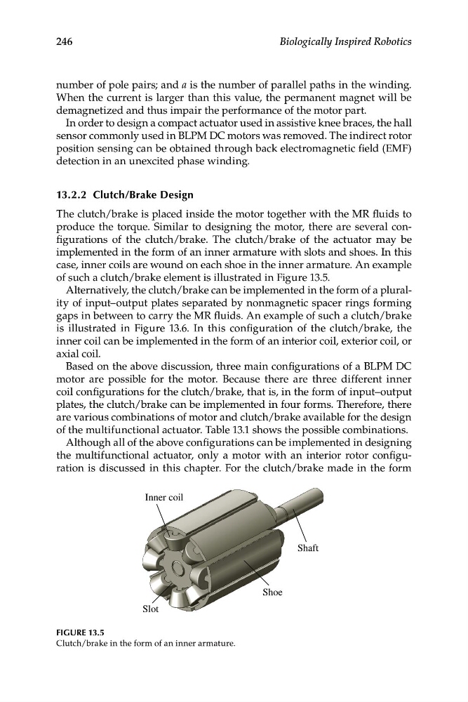
implemented in the form of an inner armature with slots and shoes. In this
case, inner coils are wound on each shoe in the inner armature. An example
of such a clutch/brake element is illustrated in Figure 13.5.
Alternatively, the clutch/brake can be implemented in the form of a plurality of input–output plates separated by nonmagnetic spacer rings forming
gaps in between to carry the MR fluids. An example of such a clutch/brake
is illustrated in Figure 13.6. In this configuration of the clutch/brake, the
inner coil can be implemented in the form of an interior coil, exterior coil, or
axial coil.
Based on the above discussion, three main configurations of a BLPM DC
motor are possible for the motor. Because there are three different inner
coil configurations for the clutch/brake, that is, in the form of input–output
plates, the clutch/brake can be implemented in four forms. Therefore, there
are various combinations of motor and clutch/brake available for the design
of the multifunctional actuator. Table 13.1 shows the possible combinations.
Although all of the above configurations can be implemented in designing
the multifunctional actuator, only a motor with an interior rotor configuration is discussed in this chapter. For the clutch/brake made in the form
Shoe
Shaft
Inner coil
Slot
FIGURE 13.5
Clutch/brake in the form of an inner armature.
Biologically Inspired Robotics
number of pole pairs; and a is the number of parallel paths in the winding.
When the current is larger than this value, the permanent magnet will be
demagnetized and thus impair the performance of the motor part.
In order to design a compact actuator used in assistive knee braces, the hall
sensor commonly used in BLPM DC motors was removed. The indirect rotor
position sensing can be obtained through back electromagnetic field (EMF)
detection in an unexcited phase winding.
13.2.2 Clutch/Brake Design
The clutch/brake is placed inside the motor together with the MR fluids to
produce the torque. Similar to designing the motor, there are several configurations of the clutch/brake. The clutch/brake of the actuator may be
implemented in the form of an inner armature with slots and shoes. In this
case, inner coils are wound on each shoe in the inner armature. An example
of such a clutch/brake element is illustrated in Figure 13.5.
Alternatively, the clutch/brake can be implemented in the form of a plurality of input–output plates separated by nonmagnetic spacer rings forming
gaps in between to carry the MR fluids. An example of such a clutch/brake
is illustrated in Figure 13.6. In this configuration of the clutch/brake, the
inner coil can be implemented in the form of an interior coil, exterior coil, or
axial coil.
Based on the above discussion, three main configurations of a BLPM DC
motor are possible for the motor. Because there are three different inner
coil configurations for the clutch/brake, that is, in the form of input–output
plates, the clutch/brake can be implemented in four forms. Therefore, there
are various combinations of motor and clutch/brake available for the design
of the multifunctional actuator. Table 13.1 shows the possible combinations.
Although all of the above configurations can be implemented in designing
the multifunctional actuator, only a motor with an interior rotor configuration is discussed in this chapter. For the clutch/brake made in the form
Shoe
Shaft
Inner coil
Slot
FIGURE 13.5
Clutch/brake in the form of an inner armature.