

Multifunctional Actuators for Assistive Knee Braces
245
where C T is the torque constant relating to the windings, I is the current
applied on the outer coils, Ф is the magnetic flux in the air gap, and the subscript M represents the motor part.
According to the Ampere’s law, there is
HL = nI = F
(13.2)
where H is the magnetic field intensity, L is the length of the magnetic circuit,
n is the turns of coil, and F is the magnetomotive force (MMF). Also,
Φ = B d
⋅ a BA
(1 3
∫
=
.3)
$
B = μH
(13.4)
where B is the magnetic flux density, A is the cross-sectional area, and μ is
the magnetic permeability. Using the above equations in the motor, it can be
derived that
∑
j
k
l
l
F
i
M
nI M =
Φ
g
=
i
= Φ M (
+ ∑
i
i
)
μ i A
μA g
μ
(13.5)
A
i i
i=1
i=1
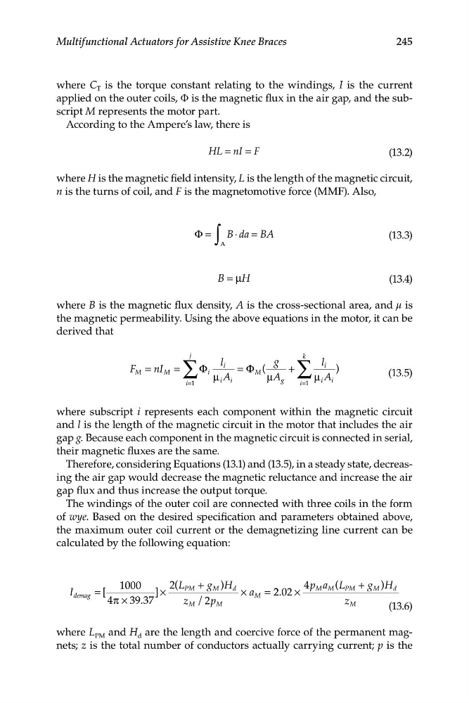
where subscript i represents each component within the magnetic circuit
and l is the length of the magnetic circuit in the motor that includes the air
gap g. Because each component in the magnetic circuit is connected in serial,
their magnetic fluxes are the same.
Therefore, considering Equations (13.1) and (13.5), in a steady state, decreasing the air gap would decrease the magnetic reluctance and increase the air
gap flux and thus increase the output torque.
The windings of the outer coil are connected with three coils in the form
of wye. Based on the desired specification and parameters obtained above,
the maximum outer coil current or the demagnetizing line current can be
calculated by the following equation:
1000
2(L + g )H
4p a
I
PM
M
d
M M ( L P M + g M )H d
demag = [
] ×
× a M = 2. 2 02 ×
4π × 39 . 37
z M / 2p M
z M
(13.6)
where L PM and H d are the length and coercive force of the permanent magnets; z is the total number of conductors actually carrying current; p is the
245
where C T is the torque constant relating to the windings, I is the current
applied on the outer coils, Ф is the magnetic flux in the air gap, and the subscript M represents the motor part.
According to the Ampere’s law, there is
HL = nI = F
(13.2)
where H is the magnetic field intensity, L is the length of the magnetic circuit,
n is the turns of coil, and F is the magnetomotive force (MMF). Also,
Φ = B d
⋅ a BA
(1 3
∫
=
.3)
$
B = μH
(13.4)
where B is the magnetic flux density, A is the cross-sectional area, and μ is
the magnetic permeability. Using the above equations in the motor, it can be
derived that
∑
j
k
l
l
F
i
M
nI M =
Φ
g
=
i
= Φ M (
+ ∑
i
i
)
μ i A
μA g
μ
(13.5)
A
i i
i=1
i=1
where subscript i represents each component within the magnetic circuit
and l is the length of the magnetic circuit in the motor that includes the air
gap g. Because each component in the magnetic circuit is connected in serial,
their magnetic fluxes are the same.
Therefore, considering Equations (13.1) and (13.5), in a steady state, decreasing the air gap would decrease the magnetic reluctance and increase the air
gap flux and thus increase the output torque.
The windings of the outer coil are connected with three coils in the form
of wye. Based on the desired specification and parameters obtained above,
the maximum outer coil current or the demagnetizing line current can be
calculated by the following equation:
1000
2(L + g )H
4p a
I
PM
M
d
M M ( L P M + g M )H d
demag = [
] ×
× a M = 2. 2 02 ×
4π × 39 . 37
z M / 2p M
z M
(13.6)
where L PM and H d are the length and coercive force of the permanent magnets; z is the total number of conductors actually carrying current; p is the