

171
Nanorobotic Manipulation for a Single Biological Cell
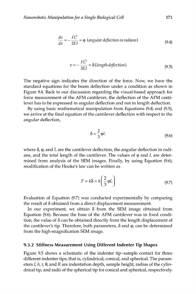
dv
FL
2
= −
= ϕ (angular deflection in radians )
(9.4)
dx
2EI
FL
3
v = −
= δ (length deflection )
(9.5)
3EI
The negative sign indicates the direction of the force. Now, we have the
standard equations for the beam deflection under a condition as shown in
Figure 9.4. Back to our discussion regarding the visual-based approach for
force measurement of the AFM cantilever, the deflection of the AFM cantilever has to be expressed in angular deflection and not in length deflection.
By using basic mathematical manipulation from Equations (9.4) and (9.5),
we arrive at the final equation of the cantilever deflection with respect to the
angular deflection,
2
δ = ϕ/
(9.6)
3
where δ, φ, and L are the cantilever deflection, the angular deflection in radians, and the total length of the cantilever. The values of φ and L are determined from analysis of the SEM images. Finally, by using Equation (9.6),
modification of the Hooke’s law can be written as
⎛ 2 ⎞
F kδ = k
=
ϕL
⎜
⎟
(9.7)
⎝ 3 ⎠
Evaluation of Equation (9.7) was conducted experimentally by comparing
the result of δ obtained from a direct displacement measurement.
In our experiment, we obtain δ from the SEM image obtained from
Equation (9.6). Because the base of the AFM cantilever was in fixed condition, the value of δ can be obtained directly from the length displacement of
the cantilever’s tip. Therefore, both parameters, δ and φ, can be determined
from the high-magnification SEM image.
9.3.2 Stiffness Measurement Using Different Indenter Tip Shapes
Figure 9.5 shows a schematic of the indenter tip–sample contact for three
different indenter tips; that is, cylindrical, conical, and spherical. The parameters I, h, r, θ, and R are indentation depth, sample height, radius of the cylindrical tip, and radii of the spherical tip for conical and spherical, respectively.
Nanorobotic Manipulation for a Single Biological Cell
dv
FL
2
= −
= ϕ (angular deflection in radians )
(9.4)
dx
2EI
FL
3
v = −
= δ (length deflection )
(9.5)
3EI
The negative sign indicates the direction of the force. Now, we have the
standard equations for the beam deflection under a condition as shown in
Figure 9.4. Back to our discussion regarding the visual-based approach for
force measurement of the AFM cantilever, the deflection of the AFM cantilever has to be expressed in angular deflection and not in length deflection.
By using basic mathematical manipulation from Equations (9.4) and (9.5),
we arrive at the final equation of the cantilever deflection with respect to the
angular deflection,
2
δ = ϕ/
(9.6)
3
where δ, φ, and L are the cantilever deflection, the angular deflection in radians, and the total length of the cantilever. The values of φ and L are determined from analysis of the SEM images. Finally, by using Equation (9.6),
modification of the Hooke’s law can be written as
⎛ 2 ⎞
F kδ = k
=
ϕL
⎜
⎟
(9.7)
⎝ 3 ⎠
Evaluation of Equation (9.7) was conducted experimentally by comparing
the result of δ obtained from a direct displacement measurement.
In our experiment, we obtain δ from the SEM image obtained from
Equation (9.6). Because the base of the AFM cantilever was in fixed condition, the value of δ can be obtained directly from the length displacement of
the cantilever’s tip. Therefore, both parameters, δ and φ, can be determined
from the high-magnification SEM image.
9.3.2 Stiffness Measurement Using Different Indenter Tip Shapes
Figure 9.5 shows a schematic of the indenter tip–sample contact for three
different indenter tips; that is, cylindrical, conical, and spherical. The parameters I, h, r, θ, and R are indentation depth, sample height, radius of the cylindrical tip, and radii of the spherical tip for conical and spherical, respectively.