

109
Development of a Low-Noise Bio-Inspired Humanoid Robot Neck
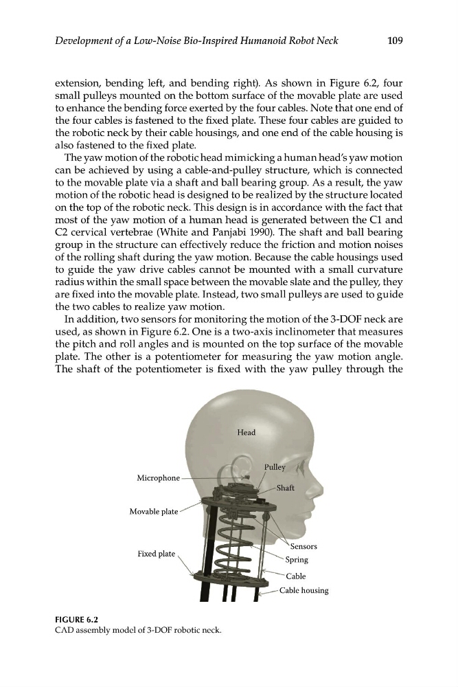
extension, bending left, and bending right). As shown in Figure 6.2, four
small pulleys mounted on the bottom surface of the movable plate are used
to enhance the bending force exerted by the four cables. Note that one end of
the four cables is fastened to the fixed plate. These four cables are guided to
the robotic neck by their cable housings, and one end of the cable housing is
also fastened to the fixed plate.
The yaw motion of the robotic head mimicking a human head’s yaw motion
can be achieved by using a cable-and-pulley structure, which is connected
to the movable plate via a shaft and ball bearing group. As a result, the yaw
motion of the robotic head is designed to be realized by the structure located
on the top of the robotic neck. This design is in accordance with the fact that
most of the yaw motion of a human head is generated between the C1 and
C2 cervical vertebrae (White and Panjabi 1990). The shaft and ball bearing
group in the structure can effectively reduce the friction and motion noises
of the rolling shaft during the yaw motion. Because the cable housings used
to guide the yaw drive cables cannot be mounted with a small curvature
radius within the small space between the movable slate and the pulley, they
are fixed into the movable plate. Instead, two small pulleys are used to guide
the two cables to realize yaw motion.
In addition, two sensors for monitoring the motion of the 3-DOF neck are
used, as shown in Figure 6.2. One is a two-axis inclinometer that measures
the pitch and roll angles and is mounted on the top surface of the movable
plate. The other is a potentiometer for measuring the yaw motion angle.
The shaft of the potentiometer is fixed with the yaw pulley through the
Head
Pulley
Microphone
Movable plate
Sensors
Spring
Cable
Cable housing
Fixed plate
Shaft
FIGURE 6.2
CAD assembly model of 3-DOF robotic neck.
Development of a Low-Noise Bio-Inspired Humanoid Robot Neck
extension, bending left, and bending right). As shown in Figure 6.2, four
small pulleys mounted on the bottom surface of the movable plate are used
to enhance the bending force exerted by the four cables. Note that one end of
the four cables is fastened to the fixed plate. These four cables are guided to
the robotic neck by their cable housings, and one end of the cable housing is
also fastened to the fixed plate.
The yaw motion of the robotic head mimicking a human head’s yaw motion
can be achieved by using a cable-and-pulley structure, which is connected
to the movable plate via a shaft and ball bearing group. As a result, the yaw
motion of the robotic head is designed to be realized by the structure located
on the top of the robotic neck. This design is in accordance with the fact that
most of the yaw motion of a human head is generated between the C1 and
C2 cervical vertebrae (White and Panjabi 1990). The shaft and ball bearing
group in the structure can effectively reduce the friction and motion noises
of the rolling shaft during the yaw motion. Because the cable housings used
to guide the yaw drive cables cannot be mounted with a small curvature
radius within the small space between the movable slate and the pulley, they
are fixed into the movable plate. Instead, two small pulleys are used to guide
the two cables to realize yaw motion.
In addition, two sensors for monitoring the motion of the 3-DOF neck are
used, as shown in Figure 6.2. One is a two-axis inclinometer that measures
the pitch and roll angles and is mounted on the top surface of the movable
plate. The other is a potentiometer for measuring the yaw motion angle.
The shaft of the potentiometer is fixed with the yaw pulley through the
Head
Pulley
Microphone
Movable plate
Sensors
Spring
Cable
Cable housing
Fixed plate
Shaft
FIGURE 6.2
CAD assembly model of 3-DOF robotic neck.