

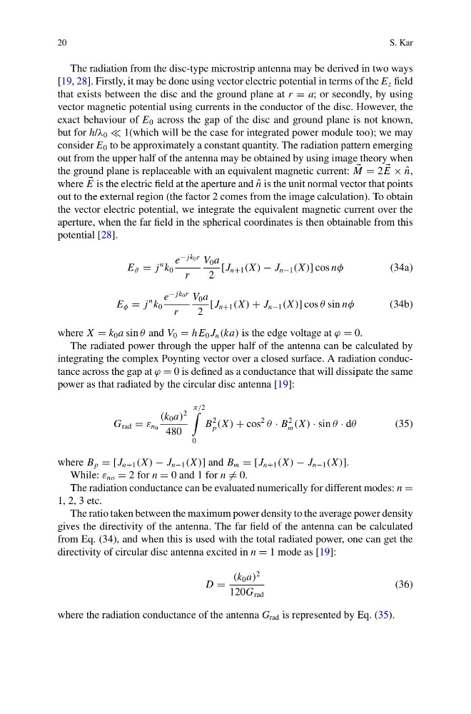
20
S. Kar
The radiation from the disc-type microstrip antenna may be derived in two ways
[19, 28]. Firstly, it may be done using vector electric potential in terms of the E z field
that exists between the disc and the ground plane at r = a; or secondly, by using
vector magnetic potential using currents in the conductor of the disc. However, the
exact behaviour of E 0 across the gap of the disc and ground plane is not known,
but for h/λ 0 1(which will be the case for integrated power module too); we may
consider E 0 to be approximately a constant quantity. The radiation pattern emerging
out from the upper half of the antenna may be obtained by using image theory when
the ground plane is replaceable with an equivalent magnetic current:
M = 2
E × ˆ
n,
where
E is the electric field at the aperture and ˆ
n is the unit normal vector that points
out to the external region (the factor 2 comes from the image calculation). To obtain
the vector electric potential, we integrate the equivalent magnetic current over the
aperture, when the far field in the spherical coordinates is then obtainable from this
potential [28].
E ϑ = j
n k 0
e
− jk 0 r
r
V 0 a
2
[J n+1 (X ) − J n−1 (X )] cos nφ
(34a)
E φ = j
n k 0
e
− jk 0 r
r
V 0 a
2
[J n+1 (X ) + J n−1 (X )] cos θ sin nφ
(34b)
where X = k 0 a sin θ and V 0 = h E 0 J n (ka) is the edge voltage at ϕ = 0.
The radiated power through the upper half of the antenna can be calculated by
integrating the complex Poynting vector over a closed surface. A radiation conductance across the gap at ϕ = 0 is defined as a conductance that will dissipate the same
power as that radiated by the circular disc antenna [19]:
G rad = ε n 0
(k 0 a)
2
480
π/2
0
B
2
p (X ) + cos
2
θ · B
2
m (X ) · sin θ · dθ
(35)
where B p = [J n+1 (X ) − J n−1 (X )] and B m = [J n+1 (X ) − J n−1 (X )].
While: ε no = 2 for n = 0 and 1 for n = 0.
The radiation conductance can be evaluated numerically for different modes: n =
1, 2, 3 etc.
The ratio taken between the maximum power density to the average power density
gives the directivity of the antenna. The far field of the antenna can be calculated
from Eq. (34), and when this is used with the total radiated power, one can get the
directivity of circular disc antenna excited in n = 1 mode as [19]:
D =
(k 0 a)
2
120G rad
(36)
where the radiation conductance of the antenna G rad is represented by Eq. (35).
S. Kar
The radiation from the disc-type microstrip antenna may be derived in two ways
[19, 28]. Firstly, it may be done using vector electric potential in terms of the E z field
that exists between the disc and the ground plane at r = a; or secondly, by using
vector magnetic potential using currents in the conductor of the disc. However, the
exact behaviour of E 0 across the gap of the disc and ground plane is not known,
but for h/λ 0 1(which will be the case for integrated power module too); we may
consider E 0 to be approximately a constant quantity. The radiation pattern emerging
out from the upper half of the antenna may be obtained by using image theory when
the ground plane is replaceable with an equivalent magnetic current:
M = 2
E × ˆ
n,
where
E is the electric field at the aperture and ˆ
n is the unit normal vector that points
out to the external region (the factor 2 comes from the image calculation). To obtain
the vector electric potential, we integrate the equivalent magnetic current over the
aperture, when the far field in the spherical coordinates is then obtainable from this
potential [28].
E ϑ = j
n k 0
e
− jk 0 r
r
V 0 a
2
[J n+1 (X ) − J n−1 (X )] cos nφ
(34a)
E φ = j
n k 0
e
− jk 0 r
r
V 0 a
2
[J n+1 (X ) + J n−1 (X )] cos θ sin nφ
(34b)
where X = k 0 a sin θ and V 0 = h E 0 J n (ka) is the edge voltage at ϕ = 0.
The radiated power through the upper half of the antenna can be calculated by
integrating the complex Poynting vector over a closed surface. A radiation conductance across the gap at ϕ = 0 is defined as a conductance that will dissipate the same
power as that radiated by the circular disc antenna [19]:
G rad = ε n 0
(k 0 a)
2
480
π/2
0
B
2
p (X ) + cos
2
θ · B
2
m (X ) · sin θ · dθ
(35)
where B p = [J n+1 (X ) − J n−1 (X )] and B m = [J n+1 (X ) − J n−1 (X )].
While: ε no = 2 for n = 0 and 1 for n = 0.
The radiation conductance can be evaluated numerically for different modes: n =
1, 2, 3 etc.
The ratio taken between the maximum power density to the average power density
gives the directivity of the antenna. The far field of the antenna can be calculated
from Eq. (34), and when this is used with the total radiated power, one can get the
directivity of circular disc antenna excited in n = 1 mode as [19]:
D =
(k 0 a)
2
120G rad
(36)
where the radiation conductance of the antenna G rad is represented by Eq. (35).