

A Novel Integrated Power Module with Solid-State …
19
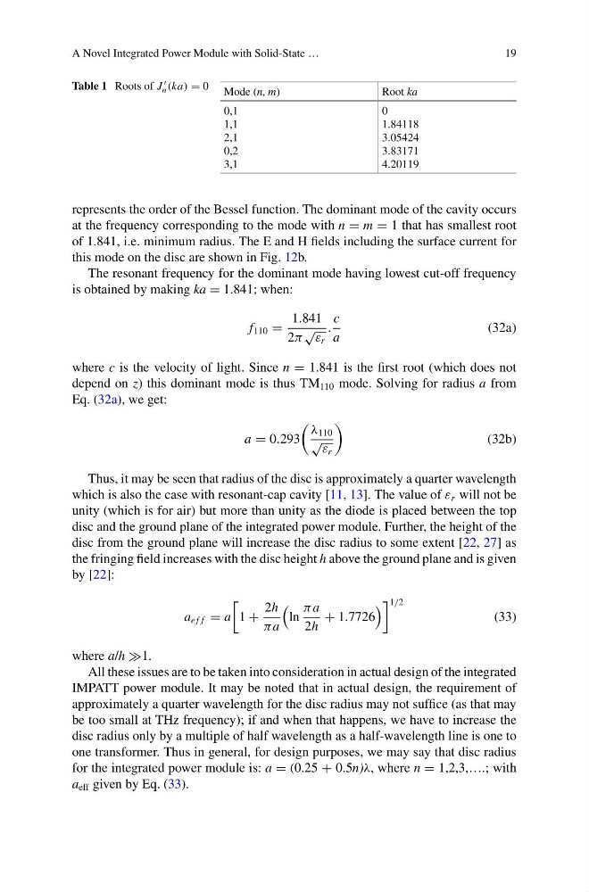
Table 1 Roots of J
n (ka) = 0 Mode (n, m)
Root ka
0,1
1,1
2,1
0,2
3,1
0
1.84118
3.05424
3.83171
4.20119
represents the order of the Bessel function. The dominant mode of the cavity occurs
at the frequency corresponding to the mode with n = m = 1 that has smallest root
of 1.841, i.e. minimum radius. The E and H fields including the surface current for
this mode on the disc are shown in Fig. 12b.
The resonant frequency for the dominant mode having lowest cut-off frequency
is obtained by making ka = 1.841; when:
f 110 =
1.841
2π
√
ε r
.
c
a
(32a)
where c is the velocity of light. Since n = 1.841 is the first root (which does not
depend on z) this dominant mode is thus TM 110 mode. Solving for radius a from
Eq. (32a), we get:
a = 0.293
λ 110
√ ε r
(32b)
Thus, it may be seen that radius of the disc is approximately a quarter wavelength
which is also the case with resonant-cap cavity [11, 13]. The value of ε r will not be
unity (which is for air) but more than unity as the diode is placed between the top
disc and the ground plane of the integrated power module. Further, the height of the
disc from the ground plane will increase the disc radius to some extent [22, 27] as
the fringing field increases with the disc height h above the ground plane and is given
by [22]:
a e f f = a
1 +
2h
πa
ln
πa
2h
+ 1.7726
1/2
(33)
where a/h 1.
All these issues are to be taken into consideration in actual design of the integrated
IMPATT power module. It may be noted that in actual design, the requirement of
approximately a quarter wavelength for the disc radius may not suffice (as that may
be too small at THz frequency); if and when that happens, we have to increase the
disc radius only by a multiple of half wavelength as a half-wavelength line is one to
one transformer. Thus in general, for design purposes, we may say that disc radius
for the integrated power module is: a = (0.25 + 0.5n)λ, where n = 1,2,3,….; with
a eff given by Eq. (33).
19
Table 1 Roots of J
n (ka) = 0 Mode (n, m)
Root ka
0,1
1,1
2,1
0,2
3,1
0
1.84118
3.05424
3.83171
4.20119
represents the order of the Bessel function. The dominant mode of the cavity occurs
at the frequency corresponding to the mode with n = m = 1 that has smallest root
of 1.841, i.e. minimum radius. The E and H fields including the surface current for
this mode on the disc are shown in Fig. 12b.
The resonant frequency for the dominant mode having lowest cut-off frequency
is obtained by making ka = 1.841; when:
f 110 =
1.841
2π
√
ε r
.
c
a
(32a)
where c is the velocity of light. Since n = 1.841 is the first root (which does not
depend on z) this dominant mode is thus TM 110 mode. Solving for radius a from
Eq. (32a), we get:
a = 0.293
λ 110
√ ε r
(32b)
Thus, it may be seen that radius of the disc is approximately a quarter wavelength
which is also the case with resonant-cap cavity [11, 13]. The value of ε r will not be
unity (which is for air) but more than unity as the diode is placed between the top
disc and the ground plane of the integrated power module. Further, the height of the
disc from the ground plane will increase the disc radius to some extent [22, 27] as
the fringing field increases with the disc height h above the ground plane and is given
by [22]:
a e f f = a
1 +
2h
πa
ln
πa
2h
+ 1.7726
1/2
(33)
where a/h 1.
All these issues are to be taken into consideration in actual design of the integrated
IMPATT power module. It may be noted that in actual design, the requirement of
approximately a quarter wavelength for the disc radius may not suffice (as that may
be too small at THz frequency); if and when that happens, we have to increase the
disc radius only by a multiple of half wavelength as a half-wavelength line is one to
one transformer. Thus in general, for design purposes, we may say that disc radius
for the integrated power module is: a = (0.25 + 0.5n)λ, where n = 1,2,3,….; with
a eff given by Eq. (33).