

18
S. Kar
5 Characterization of the Radiation Properties
of the Improvised Slotted-Disc Microstrip Patch Antenna
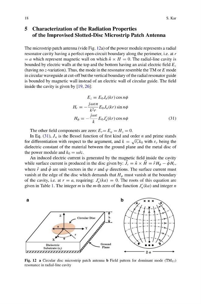
The microstrip patch antenna (vide Fig. 12a) of the power module represents a radial
resonator cavity having a perfect open-circuit boundary along the perimeter, i.e. at r
= a which represent magnetic wall on which ˆ
n × H = 0. The radial-line cavity is
bounded by electric walls at the top and the bottom having an axial electric field E z
(having no z-variation). Thus, the mode in the resonator resemble the TM or E mode
in circular waveguide at cut-off but the vertical boundary of the radial resonator guide
is bounded by magnetic wall instead of an electric wall of circular guide. The field
inside the cavity is given by [19, 26]:
E z = E 0 J n (kr) cos nφ
H r = −
jωεn
k 2 r
E 0 J n (kr) sin nφ
H φ = −
jωε
k
E 0 J
n (kr) cos nφ
(31)
The other field components are zero: E r = E ϕ = H z = 0.
In Eq. (31), J n is the Bessel function of first kind and order n and prime stands
for differentiation with respect to the argument, and k =
√ ε r k 0 with ε r being the
dielectric constant of the material between the ground plane and the metal disc of
the power module and k 0 = ω/c.
An induced electric current is generated by the magnetic field inside the cavity
while surface current is produced in the disc given by:
J s = ˆ
n ×
H = ˆ
r H φ − ˆ
φ H r ,
where ˆ
r and ˆ
φ are unit vectors in the r and ϕ directions. The surface current must
vanish at the edge of the disc which demands that H ϕ must vanish at the boundary
of the cavity, i.e. at r = a, requiring: J
n (ka) = 0. The roots of this equation are
given in Table 1. The integer m is the m-th zero of the function J
n (ka) and integer n
Fig. 12 a Circular disc microstrip patch antenna b Field pattern for dominant mode (TM 11 )
resonance in radial-line cavity
S. Kar
5 Characterization of the Radiation Properties
of the Improvised Slotted-Disc Microstrip Patch Antenna
The microstrip patch antenna (vide Fig. 12a) of the power module represents a radial
resonator cavity having a perfect open-circuit boundary along the perimeter, i.e. at r
= a which represent magnetic wall on which ˆ
n × H = 0. The radial-line cavity is
bounded by electric walls at the top and the bottom having an axial electric field E z
(having no z-variation). Thus, the mode in the resonator resemble the TM or E mode
in circular waveguide at cut-off but the vertical boundary of the radial resonator guide
is bounded by magnetic wall instead of an electric wall of circular guide. The field
inside the cavity is given by [19, 26]:
E z = E 0 J n (kr) cos nφ
H r = −
jωεn
k 2 r
E 0 J n (kr) sin nφ
H φ = −
jωε
k
E 0 J
n (kr) cos nφ
(31)
The other field components are zero: E r = E ϕ = H z = 0.
In Eq. (31), J n is the Bessel function of first kind and order n and prime stands
for differentiation with respect to the argument, and k =
√ ε r k 0 with ε r being the
dielectric constant of the material between the ground plane and the metal disc of
the power module and k 0 = ω/c.
An induced electric current is generated by the magnetic field inside the cavity
while surface current is produced in the disc given by:
J s = ˆ
n ×
H = ˆ
r H φ − ˆ
φ H r ,
where ˆ
r and ˆ
φ are unit vectors in the r and ϕ directions. The surface current must
vanish at the edge of the disc which demands that H ϕ must vanish at the boundary
of the cavity, i.e. at r = a, requiring: J
n (ka) = 0. The roots of this equation are
given in Table 1. The integer m is the m-th zero of the function J
n (ka) and integer n
Fig. 12 a Circular disc microstrip patch antenna b Field pattern for dominant mode (TM 11 )
resonance in radial-line cavity