

174
K. Mukherjee
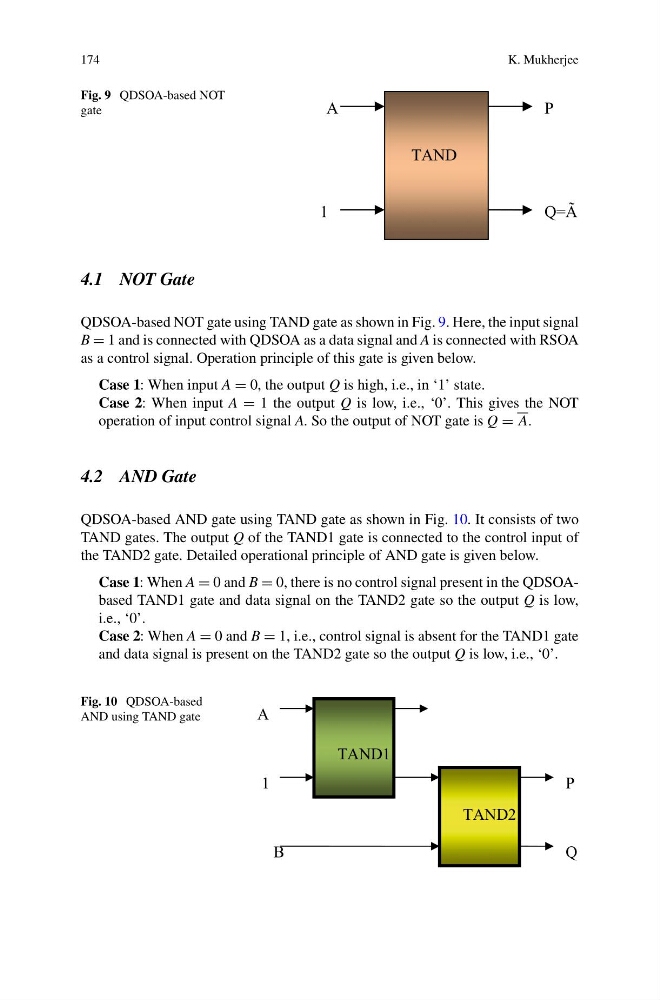
Fig. 9 QDSOA-based NOT
gate
4.1 NOT Gate
QDSOA-based NOT gate using TAND gate as shown in Fig. 9. Here, the input signal
B = 1 and is connected with QDSOA as a data signal and A is connected with RSOA
as a control signal. Operation principle of this gate is given below.
Case 1: When input A = 0, the output Q is high, i.e., in ‘1’ state.
Case 2: When input A = 1 the output Q is low, i.e., ‘0’. This gives the NOT
operation of input control signal A. So the output of NOT gate is Q = A.
4.2 AND Gate
QDSOA-based AND gate using TAND gate as shown in Fig. 10. It consists of two
TAND gates. The output Q of the TAND1 gate is connected to the control input of
the TAND2 gate. Detailed operational principle of AND gate is given below.
Case 1: When A = 0 and B = 0, there is no control signal present in the QDSOAbased TAND1 gate and data signal on the TAND2 gate so the output Q is low,
i.e., ‘0’.
Case 2: When A = 0 and B = 1, i.e., control signal is absent for the TAND1 gate
and data signal is present on the TAND2 gate so the output Q is low, i.e., ‘0’.
Fig. 10 QDSOA-based
AND using TAND gate
TAND1
A
1
TAND2
B
P
Q
K. Mukherjee
Fig. 9 QDSOA-based NOT
gate
4.1 NOT Gate
QDSOA-based NOT gate using TAND gate as shown in Fig. 9. Here, the input signal
B = 1 and is connected with QDSOA as a data signal and A is connected with RSOA
as a control signal. Operation principle of this gate is given below.
Case 1: When input A = 0, the output Q is high, i.e., in ‘1’ state.
Case 2: When input A = 1 the output Q is low, i.e., ‘0’. This gives the NOT
operation of input control signal A. So the output of NOT gate is Q = A.
4.2 AND Gate
QDSOA-based AND gate using TAND gate as shown in Fig. 10. It consists of two
TAND gates. The output Q of the TAND1 gate is connected to the control input of
the TAND2 gate. Detailed operational principle of AND gate is given below.
Case 1: When A = 0 and B = 0, there is no control signal present in the QDSOAbased TAND1 gate and data signal on the TAND2 gate so the output Q is low,
i.e., ‘0’.
Case 2: When A = 0 and B = 1, i.e., control signal is absent for the TAND1 gate
and data signal is present on the TAND2 gate so the output Q is low, i.e., ‘0’.
Fig. 10 QDSOA-based
AND using TAND gate
TAND1
A
1
TAND2
B
P
Q