

OFDM for Terahertz Wireless Communication Systems
161
OFDM Receiver
BPF
Downconversion
LNA
IF/LPF
ADC
OFDM
demodulator
+
MLSE
EsƟmaƟon
+
EqualizaƟon
DetecƟon
Data
Out
OFDM
BPF
Upconversio
PA
Cp
DAC
DifferenƟal
Encoding
Data
In
OFDM TransmiƩer
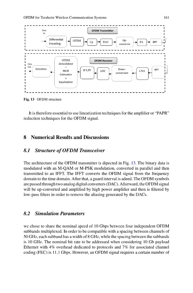
Fig. 13 OFDM structure
It is therefore essential to use linearization techniques for the amplifier or “PAPR”
reduction techniques for the OFDM signal.
8 Numerical Results and Discussions
8.1 Structure of OFDM Transceiver
The architecture of the OFDM transmitter is dipected in Fig. 13. The binary data is
modulated with an M-QAM or M-PSK modulation, converted in parallel and then
transmitted to an IFFT. The IFFT converts the OFDM signal from the frequency
domain to the time domain. After that, a guard interval is adeed. The OFDM symbols
are passed through two analog digital converters (DAC). Afterward, the OFDM signal
will be up-converted and amplified by high power amplifier and then is filtered by
low-pass filters in order to remove the aliasing generated by the DACs.
8.2 Simulation Parameters
we chose to share the nominal speed of 10 Gbps between four independent OFDM
subbands multiplexed. In order to be compatible with a spacing between channels of
50 GHz, each subband has a width of 8 GHz, while the spacing between the subbands
is 10 GHz. The nominal bit rate to be addressed when considering 10 Gb payload
Ethernet with 4% overhead dedicated to protocols and 7% for associated channel
coding (FEC) is 11.1 Gbps. However, an OFDM signal requires a certain number of
161
OFDM Receiver
BPF
Downconversion
LNA
IF/LPF
ADC
OFDM
demodulator
+
MLSE
EsƟmaƟon
+
EqualizaƟon
DetecƟon
Data
Out
OFDM
BPF
Upconversio
PA
Cp
DAC
DifferenƟal
Encoding
Data
In
OFDM TransmiƩer
Fig. 13 OFDM structure
It is therefore essential to use linearization techniques for the amplifier or “PAPR”
reduction techniques for the OFDM signal.
8 Numerical Results and Discussions
8.1 Structure of OFDM Transceiver
The architecture of the OFDM transmitter is dipected in Fig. 13. The binary data is
modulated with an M-QAM or M-PSK modulation, converted in parallel and then
transmitted to an IFFT. The IFFT converts the OFDM signal from the frequency
domain to the time domain. After that, a guard interval is adeed. The OFDM symbols
are passed through two analog digital converters (DAC). Afterward, the OFDM signal
will be up-converted and amplified by high power amplifier and then is filtered by
low-pass filters in order to remove the aliasing generated by the DACs.
8.2 Simulation Parameters
we chose to share the nominal speed of 10 Gbps between four independent OFDM
subbands multiplexed. In order to be compatible with a spacing between channels of
50 GHz, each subband has a width of 8 GHz, while the spacing between the subbands
is 10 GHz. The nominal bit rate to be addressed when considering 10 Gb payload
Ethernet with 4% overhead dedicated to protocols and 7% for associated channel
coding (FEC) is 11.1 Gbps. However, an OFDM signal requires a certain number of