

38
2 Synthesis of In-Tether Chiral Center Peptides …
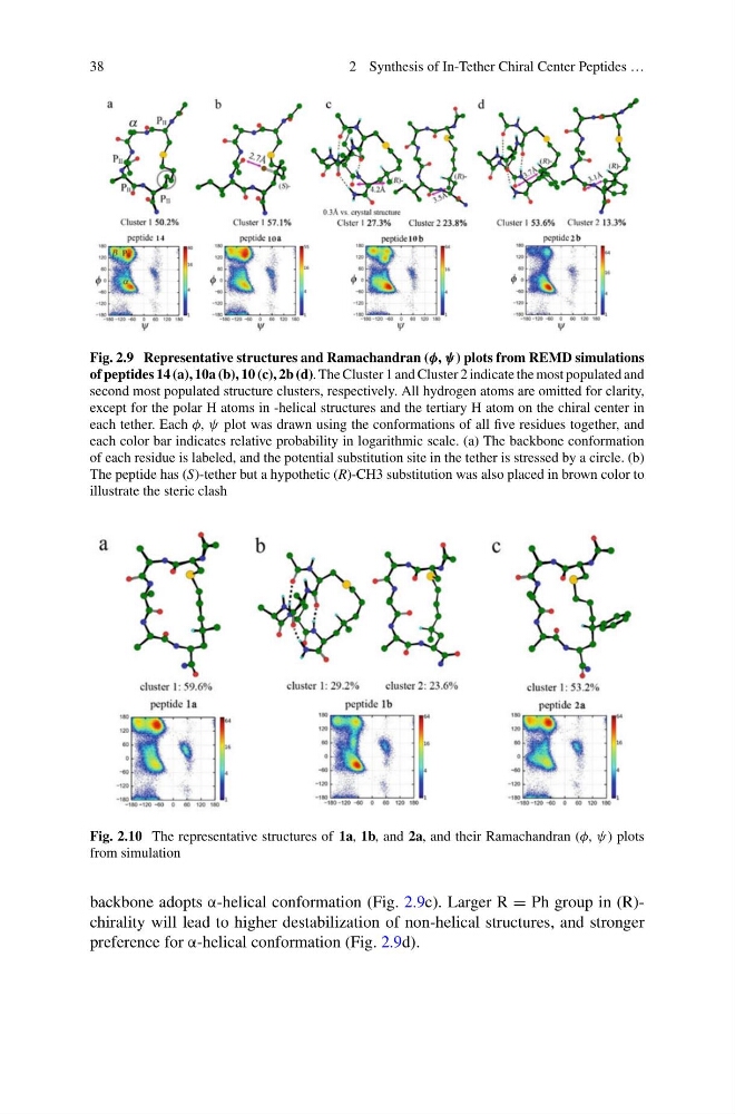
Fig. 2.9 Representative structures and Ramachandran (φ, ψ) plots from REMD simulations
of peptides 14 (a), 10a (b), 10 (c), 2b (d). The Cluster 1 and Cluster 2 indicate the most populated and
second most populated structure clusters, respectively. All hydrogen atoms are omitted for clarity,
except for the polar H atoms in -helical structures and the tertiary H atom on the chiral center in
each tether. Each φ, ψ plot was drawn using the conformations of all five residues together, and
each color bar indicates relative probability in logarithmic scale. (a) The backbone conformation
of each residue is labeled, and the potential substitution site in the tether is stressed by a circle. (b)
The peptide has (S)-tether but a hypothetic (R)-CH3 substitution was also placed in brown color to
illustrate the steric clash
Fig. 2.10 The representative structures of 1a, 1b, and 2a, and their Ramachandran (φ, ψ) plots
from simulation
backbone adopts α-helical conformation (Fig. 2.9c). Larger R = Ph group in (R)chirality will lead to higher destabilization of non-helical structures, and stronger
preference for α-helical conformation (Fig. 2.9d).
2 Synthesis of In-Tether Chiral Center Peptides …
Fig. 2.9 Representative structures and Ramachandran (φ, ψ) plots from REMD simulations
of peptides 14 (a), 10a (b), 10 (c), 2b (d). The Cluster 1 and Cluster 2 indicate the most populated and
second most populated structure clusters, respectively. All hydrogen atoms are omitted for clarity,
except for the polar H atoms in -helical structures and the tertiary H atom on the chiral center in
each tether. Each φ, ψ plot was drawn using the conformations of all five residues together, and
each color bar indicates relative probability in logarithmic scale. (a) The backbone conformation
of each residue is labeled, and the potential substitution site in the tether is stressed by a circle. (b)
The peptide has (S)-tether but a hypothetic (R)-CH3 substitution was also placed in brown color to
illustrate the steric clash
Fig. 2.10 The representative structures of 1a, 1b, and 2a, and their Ramachandran (φ, ψ) plots
from simulation
backbone adopts α-helical conformation (Fig. 2.9c). Larger R = Ph group in (R)chirality will lead to higher destabilization of non-helical structures, and stronger
preference for α-helical conformation (Fig. 2.9d).