

2 Surface Plasmons for Chiral Sensing
45
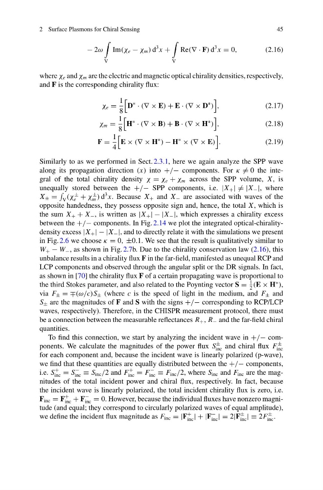
− 2ω
V
Im(χ e − χ m ) d
3 x +
V
Re(∇ · F) d
3 x = 0,
(2.16)
where χ e and χ m are the electric and magnetic optical chirality densities, respectively,
and F is the corresponding chirality flux:
χ e =
1
8
D
∗
· (∇ × E) + E · (∇ × D
∗
)
,
(2.17)
χ m =
1
8
H
∗
· (∇ × B) + B · (∇ × H
∗
)
,
(2.18)
F =
1
4
E × (∇ × H
∗
) − H
∗
× (∇ × E)
.
(2.19)
Similarly to as we performed in Sect. 2.3.1, here we again analyze the SPP wave
along its propagation direction (x) into +/− components. For κ = 0 the integral of the total chirality density χ = χ e + χ m across the SPP volume, X , is
unequally stored between the +/− SPP components, i.e. |X + | = |X − |, where
X ± =
V (χ
±
e + χ
±
m ) d
3 x. Because X + and X − are associated with waves of the
opposite handedness, they possess opposite sign and, hence, the total X , which is
the sum X + + X − , is written as |X + | − |X − |, which expresses a chirality excess
between the +/− components. In Fig. 2.14 we plot the integrated optical-chiralitydensity excess |X + | − |X − |, and to directly relate it with the simulations we present
in Fig. 2.6 we choose κ = 0, ±0.1. We see that the result is qualitatively similar to
W + − W − , as shown in Fig. 2.7b. Due to the chirality conservation law (2.16), this
unbalance results in a chirality flux F in the far-field, manifested as unequal RCP and
LCP components and observed through the angular split or the DR signals. In fact,
as shown in [70] the chirality flux F of a certain propagating wave is proportional to
the third Stokes parameter, and also related to the Poynting vector S =
1
2
(E × H
∗
),
via F ± = ∓(ω/c)S ± (where c is the speed of light in the medium, and F ± and
S ± are the magnitudes of F and S with the signs +/− corresponding to RCP/LCP
waves, respectively). Therefore, in the CHISPR measurement protocol, there must
be a connection between the measurable reflectances R + , R − and the far-field chiral
quantities.
To find this connection, we start by analyzing the incident wave in +/− components. We calculate the magnitudes of the power flux S
±
inc and chiral flux F
±
inc
for each component and, because the incident wave is linearly polarized (p-wave),
we find that these quantities are equally distributed between the +/− components,
i.e. S
+
inc = S
−
inc ≡ S inc /2 and F
+
inc = F
−
inc ≡ F inc /2, where S inc and F inc are the magnitudes of the total incident power and chiral flux, respectively. In fact, because
the incident wave is linearly polarized, the total incident chirality flux is zero, i.e.
F inc = F
+
inc + F
−
inc = 0. However, because the individual fluxes have nonzero magnitude (and equal; they correspond to circularly polarized waves of equal amplitude),
we define the incident flux magnitude as F inc = |F
+
inc | + |F
−
inc | = 2|F
±
inc | ≡ 2F
±
inc .
45
− 2ω
V
Im(χ e − χ m ) d
3 x +
V
Re(∇ · F) d
3 x = 0,
(2.16)
where χ e and χ m are the electric and magnetic optical chirality densities, respectively,
and F is the corresponding chirality flux:
χ e =
1
8
D
∗
· (∇ × E) + E · (∇ × D
∗
)
,
(2.17)
χ m =
1
8
H
∗
· (∇ × B) + B · (∇ × H
∗
)
,
(2.18)
F =
1
4
E × (∇ × H
∗
) − H
∗
× (∇ × E)
.
(2.19)
Similarly to as we performed in Sect. 2.3.1, here we again analyze the SPP wave
along its propagation direction (x) into +/− components. For κ = 0 the integral of the total chirality density χ = χ e + χ m across the SPP volume, X , is
unequally stored between the +/− SPP components, i.e. |X + | = |X − |, where
X ± =
V (χ
±
e + χ
±
m ) d
3 x. Because X + and X − are associated with waves of the
opposite handedness, they possess opposite sign and, hence, the total X , which is
the sum X + + X − , is written as |X + | − |X − |, which expresses a chirality excess
between the +/− components. In Fig. 2.14 we plot the integrated optical-chiralitydensity excess |X + | − |X − |, and to directly relate it with the simulations we present
in Fig. 2.6 we choose κ = 0, ±0.1. We see that the result is qualitatively similar to
W + − W − , as shown in Fig. 2.7b. Due to the chirality conservation law (2.16), this
unbalance results in a chirality flux F in the far-field, manifested as unequal RCP and
LCP components and observed through the angular split or the DR signals. In fact,
as shown in [70] the chirality flux F of a certain propagating wave is proportional to
the third Stokes parameter, and also related to the Poynting vector S =
1
2
(E × H
∗
),
via F ± = ∓(ω/c)S ± (where c is the speed of light in the medium, and F ± and
S ± are the magnitudes of F and S with the signs +/− corresponding to RCP/LCP
waves, respectively). Therefore, in the CHISPR measurement protocol, there must
be a connection between the measurable reflectances R + , R − and the far-field chiral
quantities.
To find this connection, we start by analyzing the incident wave in +/− components. We calculate the magnitudes of the power flux S
±
inc and chiral flux F
±
inc
for each component and, because the incident wave is linearly polarized (p-wave),
we find that these quantities are equally distributed between the +/− components,
i.e. S
+
inc = S
−
inc ≡ S inc /2 and F
+
inc = F
−
inc ≡ F inc /2, where S inc and F inc are the magnitudes of the total incident power and chiral flux, respectively. In fact, because
the incident wave is linearly polarized, the total incident chirality flux is zero, i.e.
F inc = F
+
inc + F
−
inc = 0. However, because the individual fluxes have nonzero magnitude (and equal; they correspond to circularly polarized waves of equal amplitude),
we define the incident flux magnitude as F inc = |F
+
inc | + |F
−
inc | = 2|F
±
inc | ≡ 2F
±
inc .