

2 Surface Plasmons for Chiral Sensing
35
to our CHISPR protocol. Last, in Fig. 2.4c we plot the magnitude of E y in terms of
the magnitude of κ. To quantify the results with respect to the magnitude of H y , we
normalize E y with the wave impedance ζ in water. The plot is shown in logarithmic
scale, starting from realistic values of |κ|(∼ 10
−5
) up to |κ| = 0.1, the value used in
the examples of Fig. 2.4a, b. The linearity of this scaling is a second key element to
our CHISPR protocol, as we will discuss in Sect. 2.3.
2.3 CHISPR
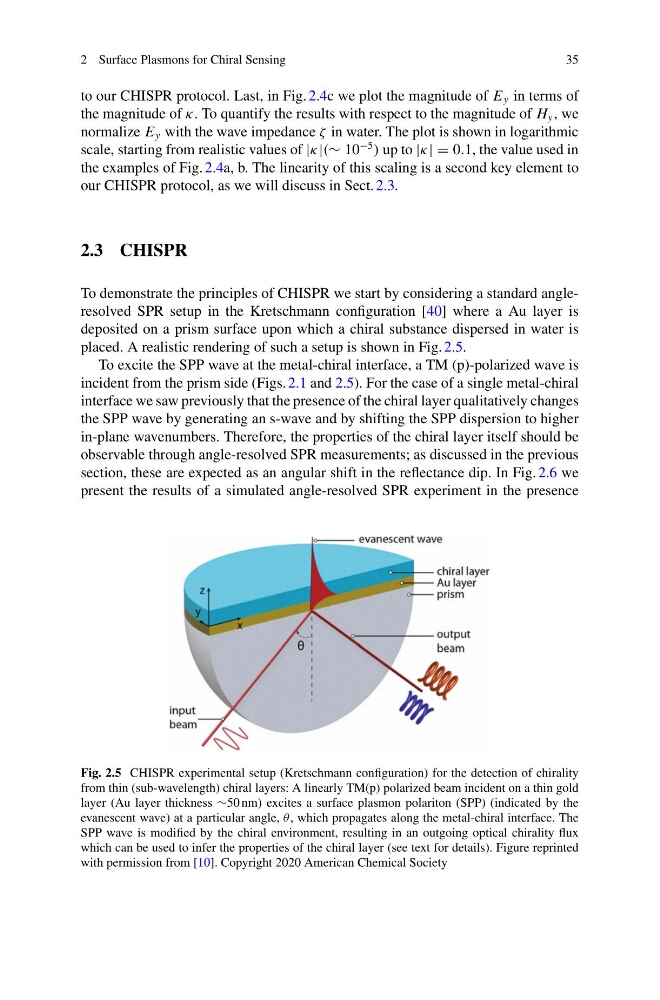
To demonstrate the principles of CHISPR we start by considering a standard angleresolved SPR setup in the Kretschmann configuration [40] where a Au layer is
deposited on a prism surface upon which a chiral substance dispersed in water is
placed. A realistic rendering of such a setup is shown in Fig. 2.5.
To excite the SPP wave at the metal-chiral interface, a TM (p)-polarized wave is
incident from the prism side (Figs. 2.1 and 2.5). For the case of a single metal-chiral
interface we saw previously that the presence of the chiral layer qualitatively changes
the SPP wave by generating an s-wave and by shifting the SPP dispersion to higher
in-plane wavenumbers. Therefore, the properties of the chiral layer itself should be
observable through angle-resolved SPR measurements; as discussed in the previous
section, these are expected as an angular shift in the reflectance dip. In Fig. 2.6 we
present the results of a simulated angle-resolved SPR experiment in the presence
Fig. 2.5 CHISPR experimental setup (Kretschmann configuration) for the detection of chirality
from thin (sub-wavelength) chiral layers: A linearly TM(p) polarized beam incident on a thin gold
layer (Au layer thickness ∼50 nm) excites a surface plasmon polariton (SPP) (indicated by the
evanescent wave) at a particular angle, θ, which propagates along the metal-chiral interface. The
SPP wave is modified by the chiral environment, resulting in an outgoing optical chirality flux
which can be used to infer the properties of the chiral layer (see text for details). Figure reprinted
with permission from [10]. Copyright 2020 American Chemical Society
35
to our CHISPR protocol. Last, in Fig. 2.4c we plot the magnitude of E y in terms of
the magnitude of κ. To quantify the results with respect to the magnitude of H y , we
normalize E y with the wave impedance ζ in water. The plot is shown in logarithmic
scale, starting from realistic values of |κ|(∼ 10
−5
) up to |κ| = 0.1, the value used in
the examples of Fig. 2.4a, b. The linearity of this scaling is a second key element to
our CHISPR protocol, as we will discuss in Sect. 2.3.
2.3 CHISPR
To demonstrate the principles of CHISPR we start by considering a standard angleresolved SPR setup in the Kretschmann configuration [40] where a Au layer is
deposited on a prism surface upon which a chiral substance dispersed in water is
placed. A realistic rendering of such a setup is shown in Fig. 2.5.
To excite the SPP wave at the metal-chiral interface, a TM (p)-polarized wave is
incident from the prism side (Figs. 2.1 and 2.5). For the case of a single metal-chiral
interface we saw previously that the presence of the chiral layer qualitatively changes
the SPP wave by generating an s-wave and by shifting the SPP dispersion to higher
in-plane wavenumbers. Therefore, the properties of the chiral layer itself should be
observable through angle-resolved SPR measurements; as discussed in the previous
section, these are expected as an angular shift in the reflectance dip. In Fig. 2.6 we
present the results of a simulated angle-resolved SPR experiment in the presence
Fig. 2.5 CHISPR experimental setup (Kretschmann configuration) for the detection of chirality
from thin (sub-wavelength) chiral layers: A linearly TM(p) polarized beam incident on a thin gold
layer (Au layer thickness ∼50 nm) excites a surface plasmon polariton (SPP) (indicated by the
evanescent wave) at a particular angle, θ, which propagates along the metal-chiral interface. The
SPP wave is modified by the chiral environment, resulting in an outgoing optical chirality flux
which can be used to infer the properties of the chiral layer (see text for details). Figure reprinted
with permission from [10]. Copyright 2020 American Chemical Society