

516
A. Karabchevsky et al.
18.4.3 Numerical Example: PT-Symmetric Coupler
This section presents an example of utilising the theory developed in the previous
section. Here, we analyse an optical system consisting of two coupled rectangular
waveguides with width w and height h separated by the distance g as schematically
shown in Fig. 18.5a. We assume that the complex refractive indices of the left (Gain)
and right (Loss) waveguides are n l = n co + iγ and n r = n co − iγ respectively. n co
is the real part of the refractive index and γ > 0 is the gain/loss (non-Hermiticity)
parameter. Thus, the system of the coupled waveguides satisfies PT-symmetry condition n(x, y) = n
∗
(−x, −y). The refractive index of the background is assumed to
be unity.
We take parameters of the waveguide coupler as g = 2 μm, w = 1 μm, h = 0.5
µm, and n co = 1.44. The coupler has two quasi-TE supermodes at this wavelength.
We calculated the field distribution of the guided modes of these waveguides, shown
in Figs. 18.3 and 18.4.
By increasing the gain/loss parameter γ the system passes through the regime of
propagation (PT-symmetric state) for two non-decaying supermodes to the regime
of decay/amplification (PT-symmetry-broken state). This behavior, shown by the
curves in Fig. 18.6.
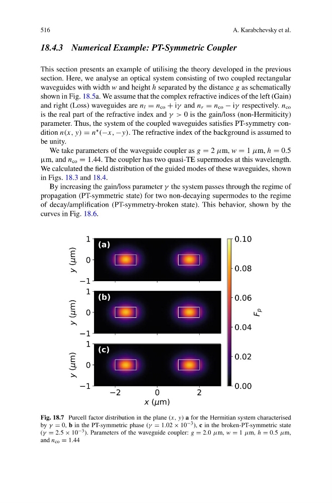
Fig. 18.7 Purcell factor distribution in the plane (x, y) a for the Hermitian system characterised
by γ = 0, b in the PT-symmetric phase (γ = 1.02 × 10 −3 ), c in the broken-PT-symmetric state
(γ = 2.5 × 10 −3 ). Parameters of the waveguide coupler: g = 2.0 μm, w = 1 μm, h = 0.5 μm,
and n co = 1.44
A. Karabchevsky et al.
18.4.3 Numerical Example: PT-Symmetric Coupler
This section presents an example of utilising the theory developed in the previous
section. Here, we analyse an optical system consisting of two coupled rectangular
waveguides with width w and height h separated by the distance g as schematically
shown in Fig. 18.5a. We assume that the complex refractive indices of the left (Gain)
and right (Loss) waveguides are n l = n co + iγ and n r = n co − iγ respectively. n co
is the real part of the refractive index and γ > 0 is the gain/loss (non-Hermiticity)
parameter. Thus, the system of the coupled waveguides satisfies PT-symmetry condition n(x, y) = n
∗
(−x, −y). The refractive index of the background is assumed to
be unity.
We take parameters of the waveguide coupler as g = 2 μm, w = 1 μm, h = 0.5
µm, and n co = 1.44. The coupler has two quasi-TE supermodes at this wavelength.
We calculated the field distribution of the guided modes of these waveguides, shown
in Figs. 18.3 and 18.4.
By increasing the gain/loss parameter γ the system passes through the regime of
propagation (PT-symmetric state) for two non-decaying supermodes to the regime
of decay/amplification (PT-symmetry-broken state). This behavior, shown by the
curves in Fig. 18.6.
Fig. 18.7 Purcell factor distribution in the plane (x, y) a for the Hermitian system characterised
by γ = 0, b in the PT-symmetric phase (γ = 1.02 × 10 −3 ), c in the broken-PT-symmetric state
(γ = 2.5 × 10 −3 ). Parameters of the waveguide coupler: g = 2.0 μm, w = 1 μm, h = 0.5 μm,
and n co = 1.44