

15 Topological Dynamics of Spin Texture Based Metamaterials
411
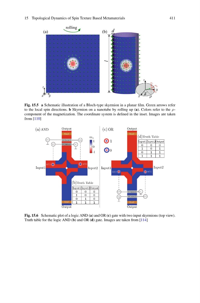
Fig. 15.5 a Schematic illustration of a Bloch-type skyrmion in a planar film. Green arrows refer
to the local spin directions. b Skyrmion on a nanotube by rolling up (a). Colors refer to the ρcomponent of the magnetization. The coordinate system is defined in the inset. Images are taken
from [110]
Input1
Input2
Output
Output
1
0
AND
OR
MTJ
MTJ
0
1
-1
m z
(a)
(b)
Input2
Input1 Input2Output
0
1
0
0
0
0
1
0
0
1
1
1
(c)
(d)
MTJ
MTJ
Input1 Input2Output
0
1
0
0
0
1
0
1
1
1
1
1
Truth Table
Truth Table
Input1
Output
Output
Fig. 15.6 Schematic plot of a logic AND (a) and OR (c) gate with two input skyrmions (top view).
Truth table for the logic AND (b) and OR (d) gate. Images are taken from [114]
411
Fig. 15.5 a Schematic illustration of a Bloch-type skyrmion in a planar film. Green arrows refer
to the local spin directions. b Skyrmion on a nanotube by rolling up (a). Colors refer to the ρcomponent of the magnetization. The coordinate system is defined in the inset. Images are taken
from [110]
Input1
Input2
Output
Output
1
0
AND
OR
MTJ
MTJ
0
1
-1
m z
(a)
(b)
Input2
Input1 Input2Output
0
1
0
0
0
0
1
0
0
1
1
1
(c)
(d)
MTJ
MTJ
Input1 Input2Output
0
1
0
0
0
1
0
1
1
1
1
1
Truth Table
Truth Table
Input1
Output
Output
Fig. 15.6 Schematic plot of a logic AND (a) and OR (c) gate with two input skyrmions (top view).
Truth table for the logic AND (b) and OR (d) gate. Images are taken from [114]