

410
Z. Li et al.
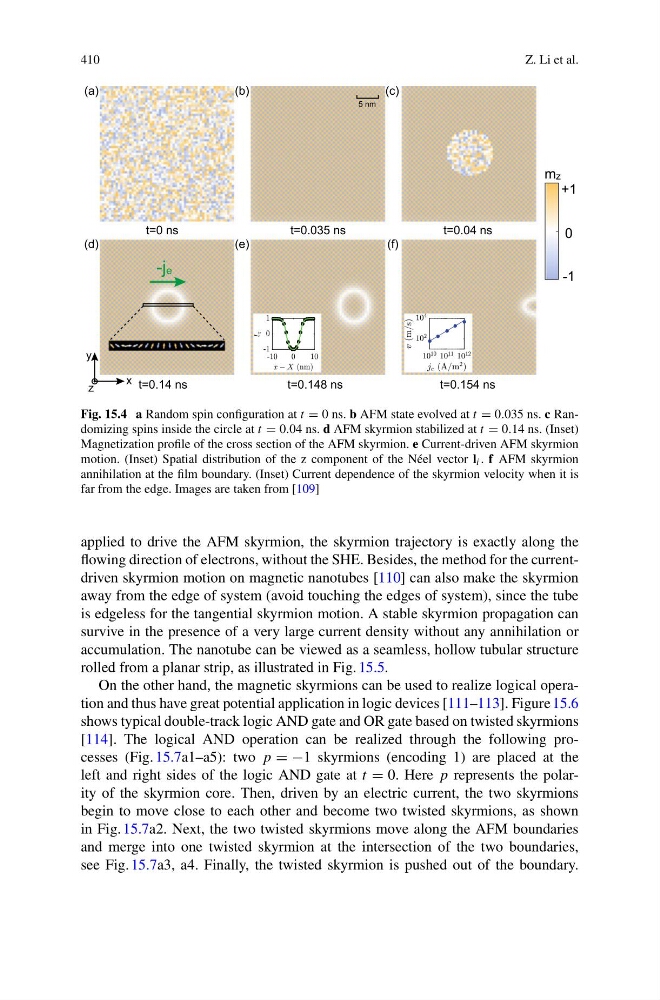
Fig. 15.4 a Random spin configuration at t = 0 ns. b AFM state evolved at t = 0.035 ns. c Randomizing spins inside the circle at t = 0.04 ns. d AFM skyrmion stabilized at t = 0.14 ns. (Inset)
Magnetization profile of the cross section of the AFM skyrmion. e Current-driven AFM skyrmion
motion. (Inset) Spatial distribution of the z component of the Néel vector l i . f AFM skyrmion
annihilation at the film boundary. (Inset) Current dependence of the skyrmion velocity when it is
far from the edge. Images are taken from [109]
applied to drive the AFM skyrmion, the skyrmion trajectory is exactly along the
flowing direction of electrons, without the SHE. Besides, the method for the currentdriven skyrmion motion on magnetic nanotubes [110] can also make the skyrmion
away from the edge of system (avoid touching the edges of system), since the tube
is edgeless for the tangential skyrmion motion. A stable skyrmion propagation can
survive in the presence of a very large current density without any annihilation or
accumulation. The nanotube can be viewed as a seamless, hollow tubular structure
rolled from a planar strip, as illustrated in Fig. 15.5.
On the other hand, the magnetic skyrmions can be used to realize logical operation and thus have great potential application in logic devices [111–113]. Figure 15.6
shows typical double-track logic AND gate and OR gate based on twisted skyrmions
[114]. The logical AND operation can be realized through the following processes (Fig. 15.7a1–a5): two p = −1 skyrmions (encoding 1) are placed at the
left and right sides of the logic AND gate at t = 0. Here p represents the polarity of the skyrmion core. Then, driven by an electric current, the two skyrmions
begin to move close to each other and become two twisted skyrmions, as shown
in Fig. 15.7a2. Next, the two twisted skyrmions move along the AFM boundaries
and merge into one twisted skyrmion at the intersection of the two boundaries,
see Fig. 15.7a3, a4. Finally, the twisted skyrmion is pushed out of the boundary.
Z. Li et al.
Fig. 15.4 a Random spin configuration at t = 0 ns. b AFM state evolved at t = 0.035 ns. c Randomizing spins inside the circle at t = 0.04 ns. d AFM skyrmion stabilized at t = 0.14 ns. (Inset)
Magnetization profile of the cross section of the AFM skyrmion. e Current-driven AFM skyrmion
motion. (Inset) Spatial distribution of the z component of the Néel vector l i . f AFM skyrmion
annihilation at the film boundary. (Inset) Current dependence of the skyrmion velocity when it is
far from the edge. Images are taken from [109]
applied to drive the AFM skyrmion, the skyrmion trajectory is exactly along the
flowing direction of electrons, without the SHE. Besides, the method for the currentdriven skyrmion motion on magnetic nanotubes [110] can also make the skyrmion
away from the edge of system (avoid touching the edges of system), since the tube
is edgeless for the tangential skyrmion motion. A stable skyrmion propagation can
survive in the presence of a very large current density without any annihilation or
accumulation. The nanotube can be viewed as a seamless, hollow tubular structure
rolled from a planar strip, as illustrated in Fig. 15.5.
On the other hand, the magnetic skyrmions can be used to realize logical operation and thus have great potential application in logic devices [111–113]. Figure 15.6
shows typical double-track logic AND gate and OR gate based on twisted skyrmions
[114]. The logical AND operation can be realized through the following processes (Fig. 15.7a1–a5): two p = −1 skyrmions (encoding 1) are placed at the
left and right sides of the logic AND gate at t = 0. Here p represents the polarity of the skyrmion core. Then, driven by an electric current, the two skyrmions
begin to move close to each other and become two twisted skyrmions, as shown
in Fig. 15.7a2. Next, the two twisted skyrmions move along the AFM boundaries
and merge into one twisted skyrmion at the intersection of the two boundaries,
see Fig. 15.7a3, a4. Finally, the twisted skyrmion is pushed out of the boundary.