

142
A. P. Pyatakov et al.
Appendix: Experimental and Calculation Details
In our experiments, the Bi-substituted rare earth iron garnet films (BiR) 3 (FeGa) 5 O 12
(R stands for rare earth) were used that were epitaxially grown on Gd 3 Ga 5 O 12
substrate by liquid-phase epitaxy (for details see elsewhere [63]). Bi substitution
allows us to obtain a clear magneto-optical image of the domain structure.
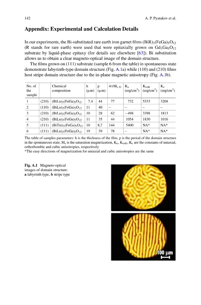
The films grown on (111) substrate (sample 6 from the table) in spontaneous state
demonstrate labyrinth-type domain structure (Fig. A.1a) while (110) and (210) films
host stripe domain structure due to the in-plane magnetic anisotropy (Fig. A.1b).
No. of
the
sample
Chemical
composition
h
(μm)
p
(μm)
4πM s, G K u
(erg/cm 3 )
K orth
(erg/cm 3 )
K c
(erg/cm 3 )
1
(210) (BiLu) 3 (FeGa) 5 O 12
7.4
44
77
732
5333
3208
2
(110) (BiLu) 3 (FeGa) 5 O 12 11
40
–
–
–
–
3
(210) (BiLu) 3 (FeGa) 5 O 12 10
28
62
−498
3398
1813
4
(210) (BiLu) 3 (FeGa) 5 O 12 11
35
44
1054
1830
1016
5
(111) (BiTm) 3 (FeGa) 5 O 12 10
8,7
144
5400
NA*
NA*
6
(111) (BiLu) 3 (FeGa) 5 O 12 19
39
78
–
NA*
NA*
The table of samples parameters: h is the thickness of the film, p is the period of the domain structure
in the spontaneous state, M s is the saturation magnetization, K u , K orth , K c are the constants of uniaxial,
orthorhombic and cubic anisotropies, respectively
*The easy directions of magnetization for uniaxial and cubic anisotropies are the same
Fig. A.1 Magneto-optical
images of domain structure:
a labyrinth type, b stripe type
A. P. Pyatakov et al.
Appendix: Experimental and Calculation Details
In our experiments, the Bi-substituted rare earth iron garnet films (BiR) 3 (FeGa) 5 O 12
(R stands for rare earth) were used that were epitaxially grown on Gd 3 Ga 5 O 12
substrate by liquid-phase epitaxy (for details see elsewhere [63]). Bi substitution
allows us to obtain a clear magneto-optical image of the domain structure.
The films grown on (111) substrate (sample 6 from the table) in spontaneous state
demonstrate labyrinth-type domain structure (Fig. A.1a) while (110) and (210) films
host stripe domain structure due to the in-plane magnetic anisotropy (Fig. A.1b).
No. of
the
sample
Chemical
composition
h
(μm)
p
(μm)
4πM s, G K u
(erg/cm 3 )
K orth
(erg/cm 3 )
K c
(erg/cm 3 )
1
(210) (BiLu) 3 (FeGa) 5 O 12
7.4
44
77
732
5333
3208
2
(110) (BiLu) 3 (FeGa) 5 O 12 11
40
–
–
–
–
3
(210) (BiLu) 3 (FeGa) 5 O 12 10
28
62
−498
3398
1813
4
(210) (BiLu) 3 (FeGa) 5 O 12 11
35
44
1054
1830
1016
5
(111) (BiTm) 3 (FeGa) 5 O 12 10
8,7
144
5400
NA*
NA*
6
(111) (BiLu) 3 (FeGa) 5 O 12 19
39
78
–
NA*
NA*
The table of samples parameters: h is the thickness of the film, p is the period of the domain structure
in the spontaneous state, M s is the saturation magnetization, K u , K orth , K c are the constants of uniaxial,
orthorhombic and cubic anisotropies, respectively
*The easy directions of magnetization for uniaxial and cubic anisotropies are the same
Fig. A.1 Magneto-optical
images of domain structure:
a labyrinth type, b stripe type