

134
A. P. Pyatakov et al.
a)
b)
Fig. 6.7 Domain walls in magnets: a Neel-type domain wall; b Bloch-type domain wall
polarization due to nonzero divergence of magnetization while for Bloch wall the
free energy term (1) remains zero.
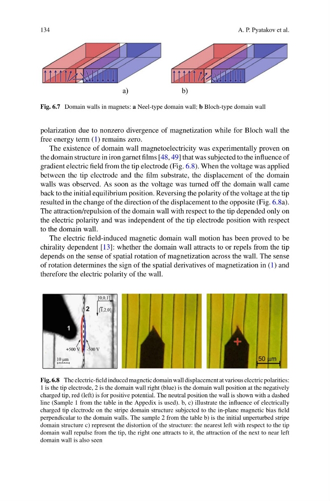
The existence of domain wall magnetoelectricity was experimentally proven on
the domain structure in iron garnet films [48, 49] that was subjected to the influence of
gradient electric field from the tip electrode (Fig. 6.8). When the voltage was applied
between the tip electrode and the film substrate, the displacement of the domain
walls was observed. As soon as the voltage was turned off the domain wall came
back to the initial equilibrium position. Reversing the polarity of the voltage at the tip
resulted in the change of the direction of the displacement to the opposite (Fig. 6.8a).
The attraction/repulsion of the domain wall with respect to the tip depended only on
the electric polarity and was independent of the tip electrode position with respect
to the domain wall.
The electric field-induced magnetic domain wall motion has been proved to be
chirality dependent [13]: whether the domain wall attracts to or repels from the tip
depends on the sense of spatial rotation of magnetization across the wall. The sense
of rotation determines the sign of the spatial derivatives of magnetization in (1) and
therefore the electric polarity of the wall.
Fig. 6.8 The electric-field induced magnetic domain wall displacement at various electric polarities:
1 is the tip electrode, 2 is the domain wall right (blue) is the domain wall position at the negatively
charged tip, red (left) is for positive potential. The neutral position the wall is shown with a dashed
line (Sample 1 from the table in the Appedix is used). b, c) illustrate the influence of electrically
charged tip electrode on the stripe domain structure subjected to the in-plane magnetic bias field
perpendicular to the domain walls. The sample 2 from the table b) is the initial unperturbed stripe
domain structure c) represent the distortion of the structure: the nearest left with respect to the tip
domain wall repulse from the tip, the right one attracts to it, the attraction of the next to near left
domain wall is also seen
A. P. Pyatakov et al.
a)
b)
Fig. 6.7 Domain walls in magnets: a Neel-type domain wall; b Bloch-type domain wall
polarization due to nonzero divergence of magnetization while for Bloch wall the
free energy term (1) remains zero.
The existence of domain wall magnetoelectricity was experimentally proven on
the domain structure in iron garnet films [48, 49] that was subjected to the influence of
gradient electric field from the tip electrode (Fig. 6.8). When the voltage was applied
between the tip electrode and the film substrate, the displacement of the domain
walls was observed. As soon as the voltage was turned off the domain wall came
back to the initial equilibrium position. Reversing the polarity of the voltage at the tip
resulted in the change of the direction of the displacement to the opposite (Fig. 6.8a).
The attraction/repulsion of the domain wall with respect to the tip depended only on
the electric polarity and was independent of the tip electrode position with respect
to the domain wall.
The electric field-induced magnetic domain wall motion has been proved to be
chirality dependent [13]: whether the domain wall attracts to or repels from the tip
depends on the sense of spatial rotation of magnetization across the wall. The sense
of rotation determines the sign of the spatial derivatives of magnetization in (1) and
therefore the electric polarity of the wall.
Fig. 6.8 The electric-field induced magnetic domain wall displacement at various electric polarities:
1 is the tip electrode, 2 is the domain wall right (blue) is the domain wall position at the negatively
charged tip, red (left) is for positive potential. The neutral position the wall is shown with a dashed
line (Sample 1 from the table in the Appedix is used). b, c) illustrate the influence of electrically
charged tip electrode on the stripe domain structure subjected to the in-plane magnetic bias field
perpendicular to the domain walls. The sample 2 from the table b) is the initial unperturbed stripe
domain structure c) represent the distortion of the structure: the nearest left with respect to the tip
domain wall repulse from the tip, the right one attracts to it, the attraction of the next to near left
domain wall is also seen