

5 Light–Nanomatter Chiral Interaction in Optical-Force Effects
117
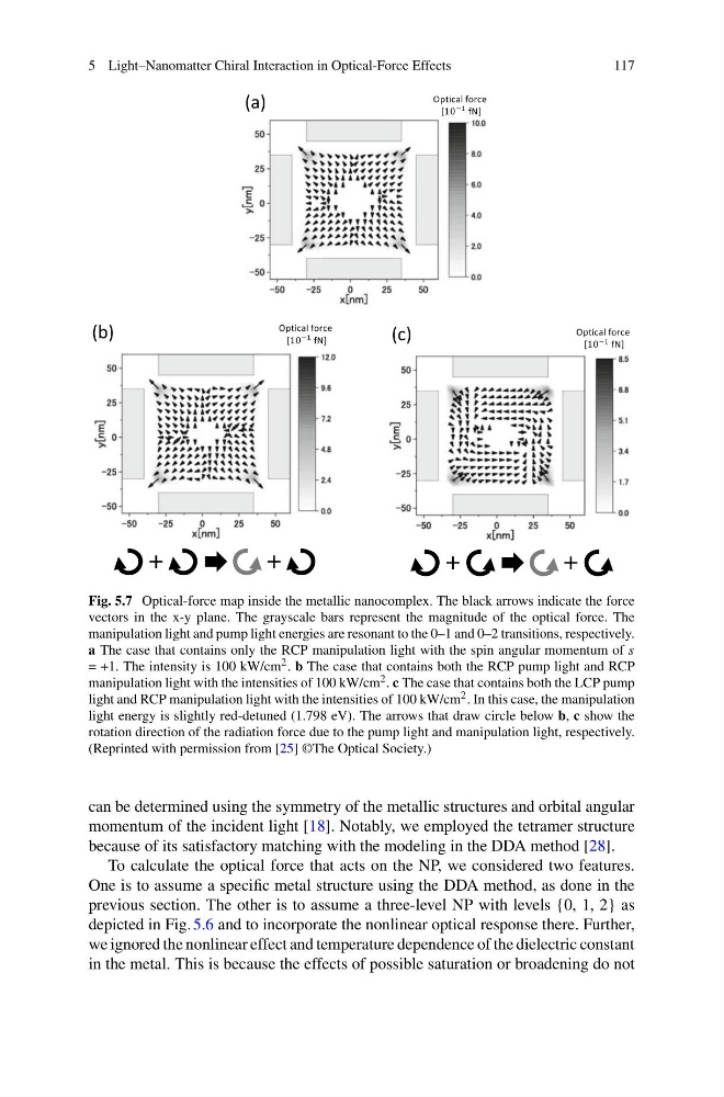
Fig. 5.7 Optical-force map inside the metallic nanocomplex. The black arrows indicate the force
vectors in the x-y plane. The grayscale bars represent the magnitude of the optical force. The
manipulation light and pump light energies are resonant to the 0–1 and 0–2 transitions, respectively.
a The case that contains only the RCP manipulation light with the spin angular momentum of s
= +1. The intensity is 100 kW/cm 2 . b The case that contains both the RCP pump light and RCP
manipulation light with the intensities of 100 kW/cm 2 . c The case that contains both the LCP pump
light and RCP manipulation light with the intensities of 100 kW/cm 2 . In this case, the manipulation
light energy is slightly red-detuned (1.798 eV). The arrows that draw circle below b, c show the
rotation direction of the radiation force due to the pump light and manipulation light, respectively.
(Reprinted with permission from [25] ©The Optical Society.)
can be determined using the symmetry of the metallic structures and orbital angular
momentum of the incident light [18]. Notably, we employed the tetramer structure
because of its satisfactory matching with the modeling in the DDA method [28].
To calculate the optical force that acts on the NP, we considered two features.
One is to assume a specific metal structure using the DDA method, as done in the
previous section. The other is to assume a three-level NP with levels {0, 1, 2} as
depicted in Fig. 5.6 and to incorporate the nonlinear optical response there. Further,
we ignored the nonlinear effect and temperature dependence of the dielectric constant
in the metal. This is because the effects of possible saturation or broadening do not
117
Fig. 5.7 Optical-force map inside the metallic nanocomplex. The black arrows indicate the force
vectors in the x-y plane. The grayscale bars represent the magnitude of the optical force. The
manipulation light and pump light energies are resonant to the 0–1 and 0–2 transitions, respectively.
a The case that contains only the RCP manipulation light with the spin angular momentum of s
= +1. The intensity is 100 kW/cm 2 . b The case that contains both the RCP pump light and RCP
manipulation light with the intensities of 100 kW/cm 2 . c The case that contains both the LCP pump
light and RCP manipulation light with the intensities of 100 kW/cm 2 . In this case, the manipulation
light energy is slightly red-detuned (1.798 eV). The arrows that draw circle below b, c show the
rotation direction of the radiation force due to the pump light and manipulation light, respectively.
(Reprinted with permission from [25] ©The Optical Society.)
can be determined using the symmetry of the metallic structures and orbital angular
momentum of the incident light [18]. Notably, we employed the tetramer structure
because of its satisfactory matching with the modeling in the DDA method [28].
To calculate the optical force that acts on the NP, we considered two features.
One is to assume a specific metal structure using the DDA method, as done in the
previous section. The other is to assume a three-level NP with levels {0, 1, 2} as
depicted in Fig. 5.6 and to incorporate the nonlinear optical response there. Further,
we ignored the nonlinear effect and temperature dependence of the dielectric constant
in the metal. This is because the effects of possible saturation or broadening do not