

264
P. Franciosi and M. Spagnuolo
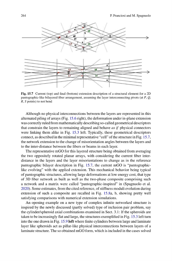
Fig. 15.7 Current (top) and final (bottom) extension description of a structural element for a 2D
pantographic-like bilayered fiber arrangement, assuming the layer interconnecting pivots (at P, Q,
R, S points) to not bend
Although no physical interconnections between the layers are represented in this
alternated piling of arrays (Fig. 15.6 right), the deformation under in-plane extension
was correctly ruled from mathematically describing so-called geometrical descriptors
that constrain the layers to remaining aligned and behave as if physical connectors
were linking them alike in Fig. 15.3 left. Typically, these geometrical descriptors
connect, as described in the minimal representative “cell” of the structure in Fig. 15.7,
the network extension to the change of misorientation angles between the layers and
to the inter-distance between the fibers or beams in each layer.
The representative mGO for this layered structure being obtained from averaging
the two oppositely rotated planar arrays, with considering the current fiber interdistance in the layers and the layer misorientations to change as in the reference
pantographic bilayer description in Fig. 15.7, the current mGO is “pantographiclike evolving” with the applied extension. This mechanical behavior being typical
of pantographic structures, allowing large deformations at low energy cost, that type
of 3D fiber network as built as well as the two-phase composite comprising such
a network and a matrix were called “pantographic-inspired” in (Spagnuolo et al.
2020). Some estimates, from the cited reference, of stiffness moduli evolution during
extension of such a composite are recalled in Fig. 15.8a, b, showing pretty well
satisfying comparisons with numerical extension simulations.
An opening example on a new type of complex infinite networked structure is
inspired by the newly discussed (partly solved) type of inclusion pair problem, say
the cylinder/spheroid axial combinations examined in Sect. 3.1: If the spheroids are
taken to be increasingly flat and large, the structures exemplified in Fig. 15.3 left turn
into the one drawn in Fig. 15.9 left where finite cylinders between large and laminate
layer like spheroids act as pillar-like physical interconnections between layers of a
laminate structure. The so obtained mGO form, which is included in the cases solved
P. Franciosi and M. Spagnuolo
Fig. 15.7 Current (top) and final (bottom) extension description of a structural element for a 2D
pantographic-like bilayered fiber arrangement, assuming the layer interconnecting pivots (at P, Q,
R, S points) to not bend
Although no physical interconnections between the layers are represented in this
alternated piling of arrays (Fig. 15.6 right), the deformation under in-plane extension
was correctly ruled from mathematically describing so-called geometrical descriptors
that constrain the layers to remaining aligned and behave as if physical connectors
were linking them alike in Fig. 15.3 left. Typically, these geometrical descriptors
connect, as described in the minimal representative “cell” of the structure in Fig. 15.7,
the network extension to the change of misorientation angles between the layers and
to the inter-distance between the fibers or beams in each layer.
The representative mGO for this layered structure being obtained from averaging
the two oppositely rotated planar arrays, with considering the current fiber interdistance in the layers and the layer misorientations to change as in the reference
pantographic bilayer description in Fig. 15.7, the current mGO is “pantographiclike evolving” with the applied extension. This mechanical behavior being typical
of pantographic structures, allowing large deformations at low energy cost, that type
of 3D fiber network as built as well as the two-phase composite comprising such
a network and a matrix were called “pantographic-inspired” in (Spagnuolo et al.
2020). Some estimates, from the cited reference, of stiffness moduli evolution during
extension of such a composite are recalled in Fig. 15.8a, b, showing pretty well
satisfying comparisons with numerical extension simulations.
An opening example on a new type of complex infinite networked structure is
inspired by the newly discussed (partly solved) type of inclusion pair problem, say
the cylinder/spheroid axial combinations examined in Sect. 3.1: If the spheroids are
taken to be increasingly flat and large, the structures exemplified in Fig. 15.3 left turn
into the one drawn in Fig. 15.9 left where finite cylinders between large and laminate
layer like spheroids act as pillar-like physical interconnections between layers of a
laminate structure. The so obtained mGO form, which is included in the cases solved