

14 Flocking Rules Governing Swarm Robot as Tool to Describe …
233
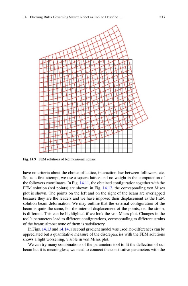
Fig. 14.9 FEM solutions of bidimensional square
have no criteria about the choice of lattice, interaction law between followers, etc.
So, as a first attempt, we use a square lattice and no weight in the computation of
the followers coordinates. In Fig. 14.11, the obtained configuration together with the
FEM solution (red points) are shown; in Fig. 14.12, the corresponding von Mises
plot is shown. The points on the left and on the right of the beam are overlapped
because they are the leaders and we have imposed their displacement as the FEM
solution beam deformation. We may outline that the external configuration of the
beam is quite the same, but the internal displacement of the points, i.e. the strain,
is different. This can be highlighted if we look the von Mises plot. Changes in the
tool’s parameters lead to different configurations, corresponding to different strains
of the beam; almost none of them is satisfactory.
In Figs. 14.13 and 14.14, a second gradient model was used; no differences can be
appreciated but a quantitative measure of the discrepancies with the FEM solutions
shows a light worsening, visible in von Mises plot.
We can try many combinations of the parameters tool to fit the deflection of our
beam but it is meaningless; we need to connect the constitutive parameters with the
233
Fig. 14.9 FEM solutions of bidimensional square
have no criteria about the choice of lattice, interaction law between followers, etc.
So, as a first attempt, we use a square lattice and no weight in the computation of
the followers coordinates. In Fig. 14.11, the obtained configuration together with the
FEM solution (red points) are shown; in Fig. 14.12, the corresponding von Mises
plot is shown. The points on the left and on the right of the beam are overlapped
because they are the leaders and we have imposed their displacement as the FEM
solution beam deformation. We may outline that the external configuration of the
beam is quite the same, but the internal displacement of the points, i.e. the strain,
is different. This can be highlighted if we look the von Mises plot. Changes in the
tool’s parameters lead to different configurations, corresponding to different strains
of the beam; almost none of them is satisfactory.
In Figs. 14.13 and 14.14, a second gradient model was used; no differences can be
appreciated but a quantitative measure of the discrepancies with the FEM solutions
shows a light worsening, visible in von Mises plot.
We can try many combinations of the parameters tool to fit the deflection of our
beam but it is meaningless; we need to connect the constitutive parameters with the