

232
R. dell’Erba
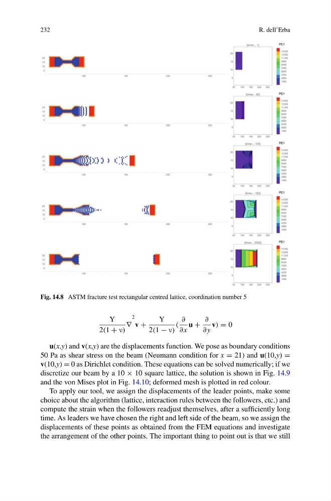
Fig. 14.8 ASTM fracture test rectangular centred lattice, coordination number 5
Y
2(1 + ν)
∇
2
v +
Y
2(1 − ν)
(
∂
∂ x
u +
∂
∂ y
v) = 0
u(x,y) and v(x,y) are the displacements function. We pose as boundary conditions
50 Pa as shear stress on the beam (Neumann condition for x = 21) and u(10,y) =
v(10,y) = 0 as Dirichlet condition. These equations can be solved numerically; if we
discretize our beam by a 10 × 10 square lattice, the solution is shown in Fig. 14.9
and the von Mises plot in Fig. 14.10; deformed mesh is plotted in red colour.
To apply our tool, we assign the displacements of the leader points, make some
choice about the algorithm (lattice, interaction rules between the followers, etc.) and
compute the strain when the followers readjust themselves, after a sufficiently long
time. As leaders we have chosen the right and left side of the beam, so we assign the
displacements of these points as obtained from the FEM equations and investigate
the arrangement of the other points. The important thing to point out is that we still
R. dell’Erba
Fig. 14.8 ASTM fracture test rectangular centred lattice, coordination number 5
Y
2(1 + ν)
∇
2
v +
Y
2(1 − ν)
(
∂
∂ x
u +
∂
∂ y
v) = 0
u(x,y) and v(x,y) are the displacements function. We pose as boundary conditions
50 Pa as shear stress on the beam (Neumann condition for x = 21) and u(10,y) =
v(10,y) = 0 as Dirichlet condition. These equations can be solved numerically; if we
discretize our beam by a 10 × 10 square lattice, the solution is shown in Fig. 14.9
and the von Mises plot in Fig. 14.10; deformed mesh is plotted in red colour.
To apply our tool, we assign the displacements of the leader points, make some
choice about the algorithm (lattice, interaction rules between the followers, etc.) and
compute the strain when the followers readjust themselves, after a sufficiently long
time. As leaders we have chosen the right and left side of the beam, so we assign the
displacements of these points as obtained from the FEM equations and investigate
the arrangement of the other points. The important thing to point out is that we still