

210
A. V. Basalin et al.
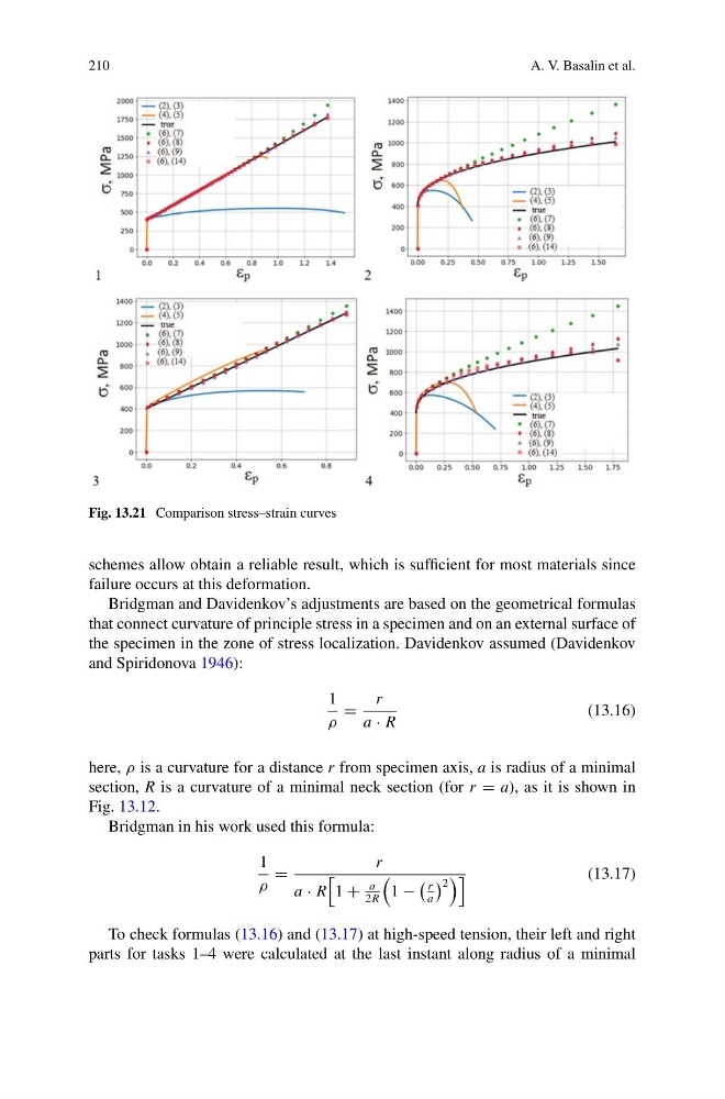
Fig. 13.21 Comparison stress–strain curves
schemes allow obtain a reliable result, which is sufficient for most materials since
failure occurs at this deformation.
Bridgman and Davidenkov’s adjustments are based on the geometrical formulas
that connect curvature of principle stress in a specimen and on an external surface of
the specimen in the zone of stress localization. Davidenkov assumed (Davidenkov
and Spiridonova 1946):
1
ρ
=
r
a · R
(13.16)
here, ρ is a curvature for a distance r from specimen axis, a is radius of a minimal
section, R is a curvature of a minimal neck section (for r = a), as it is shown in
Fig. 13.12.
Bridgman in his work used this formula:
1
ρ
=
r
a · R
1 +
a
2R
1 −
r
a
2
(13.17)
To check formulas (13.16) and (13.17) at high-speed tension, their left and right
parts for tasks 1–4 were calculated at the last instant along radius of a minimal
A. V. Basalin et al.
Fig. 13.21 Comparison stress–strain curves
schemes allow obtain a reliable result, which is sufficient for most materials since
failure occurs at this deformation.
Bridgman and Davidenkov’s adjustments are based on the geometrical formulas
that connect curvature of principle stress in a specimen and on an external surface of
the specimen in the zone of stress localization. Davidenkov assumed (Davidenkov
and Spiridonova 1946):
1
ρ
=
r
a · R
(13.16)
here, ρ is a curvature for a distance r from specimen axis, a is radius of a minimal
section, R is a curvature of a minimal neck section (for r = a), as it is shown in
Fig. 13.12.
Bridgman in his work used this formula:
1
ρ
=
r
a · R
1 +
a
2R
1 −
r
a
2
(13.17)
To check formulas (13.16) and (13.17) at high-speed tension, their left and right
parts for tasks 1–4 were calculated at the last instant along radius of a minimal