

13 High Strain Rate Tension Experiments Features …
197
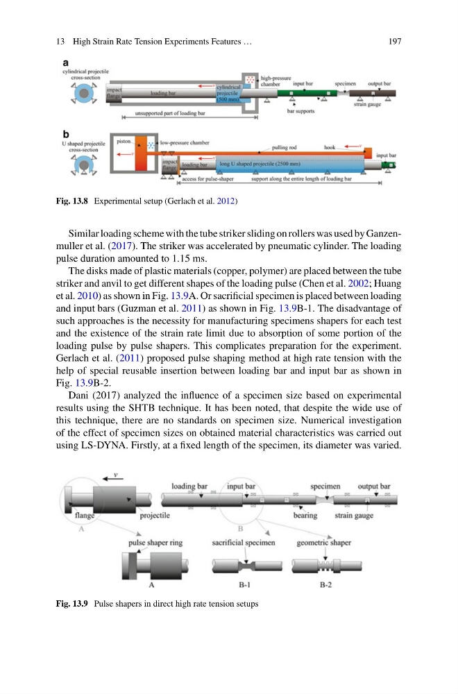
Fig. 13.8 Experimental setup (Gerlach et al. 2012)
Similar loading scheme with the tube striker sliding on rollers was used by Ganzenmuller et al. (2017). The striker was accelerated by pneumatic cylinder. The loading
pulse duration amounted to 1.15 ms.
The disks made of plastic materials (copper, polymer) are placed between the tube
striker and anvil to get different shapes of the loading pulse (Chen et al. 2002; Huang
et al. 2010) as shown in Fig. 13.9A. Or sacrificial specimen is placed between loading
and input bars (Guzman et al. 2011) as shown in Fig. 13.9B-1. The disadvantage of
such approaches is the necessity for manufacturing specimens shapers for each test
and the existence of the strain rate limit due to absorption of some portion of the
loading pulse by pulse shapers. This complicates preparation for the experiment.
Gerlach et al. (2011) proposed pulse shaping method at high rate tension with the
help of special reusable insertion between loading bar and input bar as shown in
Fig. 13.9B-2.
Dani (2017) analyzed the influence of a specimen size based on experimental
results using the SHTB technique. It has been noted, that despite the wide use of
this technique, there are no standards on specimen size. Numerical investigation
of the effect of specimen sizes on obtained material characteristics was carried out
using LS-DYNA. Firstly, at a fixed length of the specimen, its diameter was varied.
Fig. 13.9 Pulse shapers in direct high rate tension setups
197
Fig. 13.8 Experimental setup (Gerlach et al. 2012)
Similar loading scheme with the tube striker sliding on rollers was used by Ganzenmuller et al. (2017). The striker was accelerated by pneumatic cylinder. The loading
pulse duration amounted to 1.15 ms.
The disks made of plastic materials (copper, polymer) are placed between the tube
striker and anvil to get different shapes of the loading pulse (Chen et al. 2002; Huang
et al. 2010) as shown in Fig. 13.9A. Or sacrificial specimen is placed between loading
and input bars (Guzman et al. 2011) as shown in Fig. 13.9B-1. The disadvantage of
such approaches is the necessity for manufacturing specimens shapers for each test
and the existence of the strain rate limit due to absorption of some portion of the
loading pulse by pulse shapers. This complicates preparation for the experiment.
Gerlach et al. (2011) proposed pulse shaping method at high rate tension with the
help of special reusable insertion between loading bar and input bar as shown in
Fig. 13.9B-2.
Dani (2017) analyzed the influence of a specimen size based on experimental
results using the SHTB technique. It has been noted, that despite the wide use of
this technique, there are no standards on specimen size. Numerical investigation
of the effect of specimen sizes on obtained material characteristics was carried out
using LS-DYNA. Firstly, at a fixed length of the specimen, its diameter was varied.
Fig. 13.9 Pulse shapers in direct high rate tension setups