

12 The Dynamics of Eccentric Vibration Mechanism (Part 2)
183
12.5.3 Bifurcation Diagrams
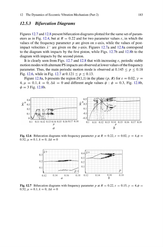
Figures 12.7 and 12.8 present bifurcation diagrams plotted for the same set of parameters as in Fig. 12.4, but at R = 0.22 and for two parameter values ε, in which the
values of the frequency parameter p are given on x-axis, while the values of postimpact velocities ˙
x
+ are given on the y-axis. Figures 12.7a and 12.8a correspond
to the diagram with impacts by the first piston, while Figs. 12.7b and 12.8b to the
diagram with impacts by the second piston.
It is clearly seen from Figs. 12.7 and 12.8 that with increasing ε, periodic stable
motion modes with alternate PS impacts are observed at lower values of the frequency
parameter. Thus, the main periodic motion mode is observed at 0.145 ≤ p ≤ 0.18
Fig. 12.6, while in Fig. 12.7 at 0.121 ≤ p ≤ 0.13.
Figure 12.8a, b presents the region D(1,1) in the plane ( p, R) for ε = 0.02, γ =
4, μ = 0.1, k = 0, ,k = 0 and different angle values φ : φ = 0.3, Fig. 12.8b,
φ = 3 Fig. 12.8b.
а
b
Fig. 12.6 Bifurcation diagrams with frequency parameter p at R = 0.22, ε = 0.02, γ = 4,φ =
0.52, μ = 0.1, k = 0, ,k = 0
а
b
Fig. 12.7 Bifurcation diagrams with frequency parameter p at R = 0.22, ε = 0.15, γ = 4,φ =
0.52, μ = 0.1, k = 0, ,k = 0
183
12.5.3 Bifurcation Diagrams
Figures 12.7 and 12.8 present bifurcation diagrams plotted for the same set of parameters as in Fig. 12.4, but at R = 0.22 and for two parameter values ε, in which the
values of the frequency parameter p are given on x-axis, while the values of postimpact velocities ˙
x
+ are given on the y-axis. Figures 12.7a and 12.8a correspond
to the diagram with impacts by the first piston, while Figs. 12.7b and 12.8b to the
diagram with impacts by the second piston.
It is clearly seen from Figs. 12.7 and 12.8 that with increasing ε, periodic stable
motion modes with alternate PS impacts are observed at lower values of the frequency
parameter. Thus, the main periodic motion mode is observed at 0.145 ≤ p ≤ 0.18
Fig. 12.6, while in Fig. 12.7 at 0.121 ≤ p ≤ 0.13.
Figure 12.8a, b presents the region D(1,1) in the plane ( p, R) for ε = 0.02, γ =
4, μ = 0.1, k = 0, ,k = 0 and different angle values φ : φ = 0.3, Fig. 12.8b,
φ = 3 Fig. 12.8b.
а
b
Fig. 12.6 Bifurcation diagrams with frequency parameter p at R = 0.22, ε = 0.02, γ = 4,φ =
0.52, μ = 0.1, k = 0, ,k = 0
а
b
Fig. 12.7 Bifurcation diagrams with frequency parameter p at R = 0.22, ε = 0.15, γ = 4,φ =
0.52, μ = 0.1, k = 0, ,k = 0