

130
N. A. Abrosimov et al.
time, for the integration of which the explicit “cross” scheme is used (Abrosimov and
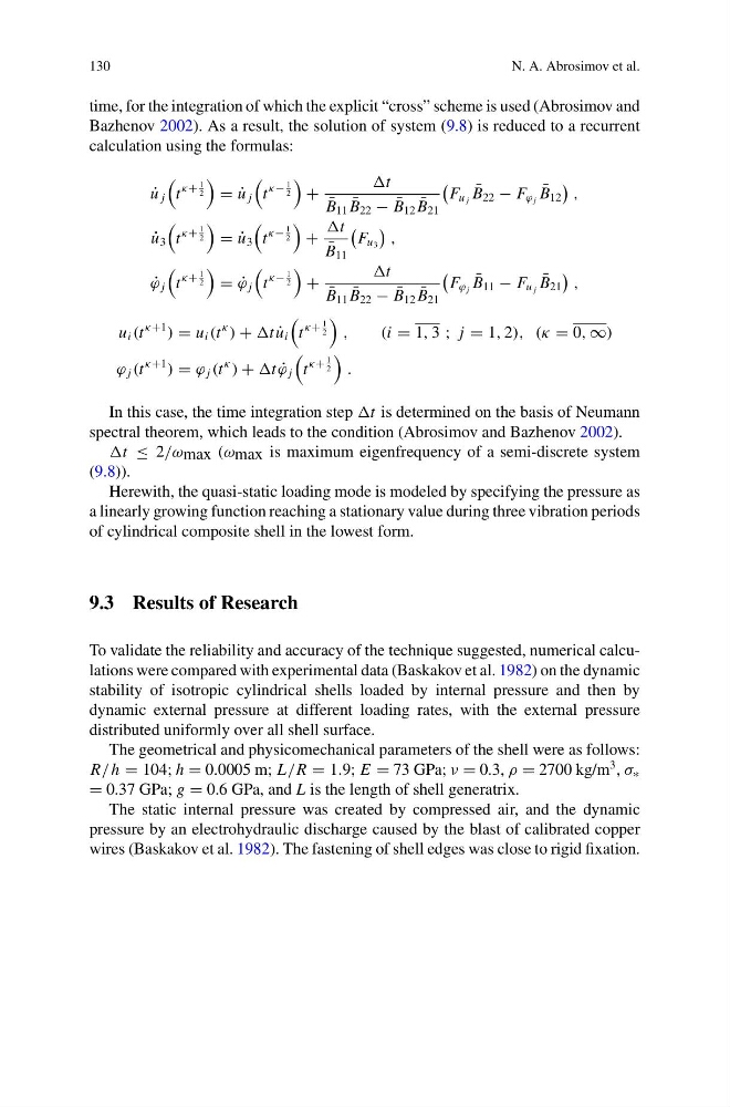
Bazhenov 2002). As a result, the solution of system (9.8) is reduced to a recurrent
calculation using the formulas:
˙
u j
t
κ+
1
2
= ˙
u j
t
κ−
1
2
+
t
¯
B 11 ¯
B 22 − ¯
B 12 ¯
B 21
F u j ¯
B 22 − F ϕ j ¯
B 12
,
˙
u 3
t
κ+
1
2
= ˙
u 3
t
κ−
1
2
+
t
¯
B 11
F u 3
,
˙
ϕ j
t
κ+
1
2
= ˙
ϕ j
t
κ−
1
2
+
t
¯
B 11 ¯
B 22 − ¯
B 12 ¯
B 21
F ϕ j ¯
B 11 − F u j ¯
B 21
,
u i (t
κ+1
) = u i (t
κ
) + t ˙
u i
t
κ+
1
2
,
(i = 1, 3 ; j = 1, 2), (κ = 0, ∞)
ϕ j (t
κ+1
) = ϕ j (t
κ
) + t ˙
ϕ j
t
κ+
1
2
.
In this case, the time integration step t is determined on the basis of Neumann
spectral theorem, which leads to the condition (Abrosimov and Bazhenov 2002).
t ≤ 2/ω max (ω max is maximum eigenfrequency of a semi-discrete system
(9.8)).
Herewith, the quasi-static loading mode is modeled by specifying the pressure as
a linearly growing function reaching a stationary value during three vibration periods
of cylindrical composite shell in the lowest form.
9.3 Results of Research
To validate the reliability and accuracy of the technique suggested, numerical calculations were compared with experimental data (Baskakov et al. 1982) on the dynamic
stability of isotropic cylindrical shells loaded by internal pressure and then by
dynamic external pressure at different loading rates, with the external pressure
distributed uniformly over all shell surface.
The geometrical and physicomechanical parameters of the shell were as follows:
R/ h = 104; h = 0.0005 m; L/R = 1.9; E = 73 GPa; ν = 0.3, ρ = 2700 kg/m
3 , σ ∗
= 0.37 GPa; g = 0.6 GPa, and L is the length of shell generatrix.
The static internal pressure was created by compressed air, and the dynamic
pressure by an electrohydraulic discharge caused by the blast of calibrated copper
wires (Baskakov et al. 1982). The fastening of shell edges was close to rigid fixation.
N. A. Abrosimov et al.
time, for the integration of which the explicit “cross” scheme is used (Abrosimov and
Bazhenov 2002). As a result, the solution of system (9.8) is reduced to a recurrent
calculation using the formulas:
˙
u j
t
κ+
1
2
= ˙
u j
t
κ−
1
2
+
t
¯
B 11 ¯
B 22 − ¯
B 12 ¯
B 21
F u j ¯
B 22 − F ϕ j ¯
B 12
,
˙
u 3
t
κ+
1
2
= ˙
u 3
t
κ−
1
2
+
t
¯
B 11
F u 3
,
˙
ϕ j
t
κ+
1
2
= ˙
ϕ j
t
κ−
1
2
+
t
¯
B 11 ¯
B 22 − ¯
B 12 ¯
B 21
F ϕ j ¯
B 11 − F u j ¯
B 21
,
u i (t
κ+1
) = u i (t
κ
) + t ˙
u i
t
κ+
1
2
,
(i = 1, 3 ; j = 1, 2), (κ = 0, ∞)
ϕ j (t
κ+1
) = ϕ j (t
κ
) + t ˙
ϕ j
t
κ+
1
2
.
In this case, the time integration step t is determined on the basis of Neumann
spectral theorem, which leads to the condition (Abrosimov and Bazhenov 2002).
t ≤ 2/ω max (ω max is maximum eigenfrequency of a semi-discrete system
(9.8)).
Herewith, the quasi-static loading mode is modeled by specifying the pressure as
a linearly growing function reaching a stationary value during three vibration periods
of cylindrical composite shell in the lowest form.
9.3 Results of Research
To validate the reliability and accuracy of the technique suggested, numerical calculations were compared with experimental data (Baskakov et al. 1982) on the dynamic
stability of isotropic cylindrical shells loaded by internal pressure and then by
dynamic external pressure at different loading rates, with the external pressure
distributed uniformly over all shell surface.
The geometrical and physicomechanical parameters of the shell were as follows:
R/ h = 104; h = 0.0005 m; L/R = 1.9; E = 73 GPa; ν = 0.3, ρ = 2700 kg/m
3 , σ ∗
= 0.37 GPa; g = 0.6 GPa, and L is the length of shell generatrix.
The static internal pressure was created by compressed air, and the dynamic
pressure by an electrohydraulic discharge caused by the blast of calibrated copper
wires (Baskakov et al. 1982). The fastening of shell edges was close to rigid fixation.