

111
chance of this happening is just too small. Even with the greatest
care in assembling them, all crystals contain dislocations (also see
Section 4.2).
It is dislocation that makes metals soft and ductile. Recall that the
strength of a perfect crystal computed from interatomic forces gives
an “ideal strength” around E/15 but that the strengths of real engineering materials are much less. This was a mystery until halfway
through the last century—a mere 60 years ago—when an Englishman, Geoffrey Taylor, and a Hungarian, Egon Orowan, realized that
a “dislocated” crystal could deform at stresses far below the ideal
strength. When a dislocation moves, it makes the material above
the slip plane slide relative to that below, producing a shear strain.
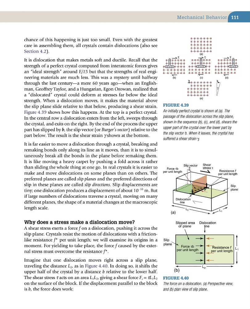
Figure 4.39 shows how this happens. At the top is a perfect crystal.
In the central row a dislocation enters from the left, sweeps through
the crystal, and exits on the right. By the end of the process the upper
part has slipped by b, the slip vector (or Burger’s vector) relative to the
part below. The result is the shear strain γ shown at the bottom.
It is far easier to move a dislocation through a crystal, breaking and
remaking bonds only along its line as it moves, than it is to simultaneously break all the bonds in the plane before remaking them.
It is like moving a heavy carpet by pushing a fold across it rather
than sliding the whole thing at one go. In real crystals it is easier to
make and move dislocations on some planes than on others. The
preferred planes are called slip planes and the preferred directions of
slip in these planes are called slip directions. Slip displacements are
tiny; one dislocation produces a displacement of about 10
−10 m. But
if large numbers of dislocations traverse a crystal, moving on many
different planes, the shape of a material changes at the macroscopic
length scale.
Why does a stress make a dislocation move?
A shear stress exerts a force f on a dislocation, pushing it across the
slip plane. Crystals resist the motion of dislocations with a frictionlike resistance f* per unit length; we will examine its origins in a
moment. For yielding to take place, the force f caused by the external stress must overcome the resistance f*.
Imagine that one dislocation moves right across a slip plane,
traveling the distance L 2 , as in Figure 4.40. In doing so, it shifts the
upper half of the crystal by a distance b relative to the lower half.
The shear stress τ acts on an area L 1 L 2 , giving a shear force F s = τL 1 L 2
on the surface of the block. If the displacement parallel to the block
is b, the force does work:
Mechanical Behavior
Figure 4.39
An initially perfect crystal is shown at (a). The
passage of the dislocation across the slip plane,
shown in the sequence (b), (c), and (d), shears the
upper part of the crystal over the lower part by
the slip vector b. When it leaves, the crystal has
suffered a shear strain γ.
(a)
(b)
(c)
(d)
(e)
τ
τ
τ
b
b
γ
Figure 4.40
The force on a dislocation. (a) Perspective view,
and (b) plan view of slip plane.
(a)
Slip
plane
Slip
plane
(b)
Dislocation
line
Force τb
per unit length
b
Slip vector
Resistance f
per unit length
Shear
stress τ
L 1
L 2
Force τb
per unit length
Resistance f
per unit length
Dislocation
line
Slipped area
of plane
L 2
L 1
chance of this happening is just too small. Even with the greatest
care in assembling them, all crystals contain dislocations (also see
Section 4.2).
It is dislocation that makes metals soft and ductile. Recall that the
strength of a perfect crystal computed from interatomic forces gives
an “ideal strength” around E/15 but that the strengths of real engineering materials are much less. This was a mystery until halfway
through the last century—a mere 60 years ago—when an Englishman, Geoffrey Taylor, and a Hungarian, Egon Orowan, realized that
a “dislocated” crystal could deform at stresses far below the ideal
strength. When a dislocation moves, it makes the material above
the slip plane slide relative to that below, producing a shear strain.
Figure 4.39 shows how this happens. At the top is a perfect crystal.
In the central row a dislocation enters from the left, sweeps through
the crystal, and exits on the right. By the end of the process the upper
part has slipped by b, the slip vector (or Burger’s vector) relative to the
part below. The result is the shear strain γ shown at the bottom.
It is far easier to move a dislocation through a crystal, breaking and
remaking bonds only along its line as it moves, than it is to simultaneously break all the bonds in the plane before remaking them.
It is like moving a heavy carpet by pushing a fold across it rather
than sliding the whole thing at one go. In real crystals it is easier to
make and move dislocations on some planes than on others. The
preferred planes are called slip planes and the preferred directions of
slip in these planes are called slip directions. Slip displacements are
tiny; one dislocation produces a displacement of about 10
−10 m. But
if large numbers of dislocations traverse a crystal, moving on many
different planes, the shape of a material changes at the macroscopic
length scale.
Why does a stress make a dislocation move?
A shear stress exerts a force f on a dislocation, pushing it across the
slip plane. Crystals resist the motion of dislocations with a frictionlike resistance f* per unit length; we will examine its origins in a
moment. For yielding to take place, the force f caused by the external stress must overcome the resistance f*.
Imagine that one dislocation moves right across a slip plane,
traveling the distance L 2 , as in Figure 4.40. In doing so, it shifts the
upper half of the crystal by a distance b relative to the lower half.
The shear stress τ acts on an area L 1 L 2 , giving a shear force F s = τL 1 L 2
on the surface of the block. If the displacement parallel to the block
is b, the force does work:
Mechanical Behavior
Figure 4.39
An initially perfect crystal is shown at (a). The
passage of the dislocation across the slip plane,
shown in the sequence (b), (c), and (d), shears the
upper part of the crystal over the lower part by
the slip vector b. When it leaves, the crystal has
suffered a shear strain γ.
(a)
(b)
(c)
(d)
(e)
τ
τ
τ
b
b
γ
Figure 4.40
The force on a dislocation. (a) Perspective view,
and (b) plan view of slip plane.
(a)
Slip
plane
Slip
plane
(b)
Dislocation
line
Force τb
per unit length
b
Slip vector
Resistance f
per unit length
Shear
stress τ
L 1
L 2
Force τb
per unit length
Resistance f
per unit length
Dislocation
line
Slipped area
of plane
L 2
L 1