

C hapter 4 Material Classes, structure, and properties
112
W
L L b
= τ 1 2
(4.16)
This work is done against the resistance f* per unit length, or f*L 1
on the length L 1 , and it does so over a displacement L 2 (because the
dislocation line moves this far against f*), giving total work against
f* of f*L 1 L 2 . Equating this to the work W done by the applied stress
τ gives
τb f
= *
(4.17)
So, provided the shear stress τ exceeds the value f*/b, it will make
dislocations move and cause the crystal to shear. The way to make
it stronger is to increase this resisting force, and that is where the
nanoscale comes in. We look first at the oldest of the nanostructuring schemes: dispersion hardening.
strengthening mechanisms
As we have seen, dislocations distort the crystal locally, and the
local distortion has an associated energy. This gives the dislocation a line tension—the equivalent, for a line, of the surface tension
of a liquid. If the crystal is perfectly regular, a dislocation can
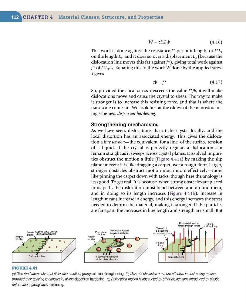
remain straight as it sweeps across crystal planes. Dissolved impurities obstruct the motion a little (Figure 4.41a) by making the slip
plane uneven; it is like dragging a carpet over a rough floor. Larger,
stronger obstacles obstruct motion much more effectively—more
like pinning the carpet down with tacks, though here the analogy is
less good. To get real: It is because, when strong obstacles are placed
in its path, the dislocation must bend between and around them,
and in doing so its length increases (Figure 4.41b). Increase in
length means increase in energy, and this energy increases the stress
needed to deform the material, making it stronger. If the particles
are far apart, the increases in line length and strength are small. But
Figure 4.41
(a) Dissolved atoms obstruct dislocation motion, giving solution strengthening. (b) Discrete obstacles are more effective in obstructing motion,
provided their spacing is nanoscale, giving dispersion hardening. (c) Dislocation motion is obstructed by other dislocations introduced by plastic
deformation, giving work hardening.
Solute
atoms
Region
of slip
Dislocation line
Applied stess pushes
dislocation forward
Precipitate
particle
Region
of slip
Successive positions
of the dislocation line
Dislocation forced
between particles
Moving dislocation
forced through forest
Forest
dislocations
Region
of slip
Dislocation line
“Forest” of
dislocations
act as obstacles
112
W
L L b
= τ 1 2
(4.16)
This work is done against the resistance f* per unit length, or f*L 1
on the length L 1 , and it does so over a displacement L 2 (because the
dislocation line moves this far against f*), giving total work against
f* of f*L 1 L 2 . Equating this to the work W done by the applied stress
τ gives
τb f
= *
(4.17)
So, provided the shear stress τ exceeds the value f*/b, it will make
dislocations move and cause the crystal to shear. The way to make
it stronger is to increase this resisting force, and that is where the
nanoscale comes in. We look first at the oldest of the nanostructuring schemes: dispersion hardening.
strengthening mechanisms
As we have seen, dislocations distort the crystal locally, and the
local distortion has an associated energy. This gives the dislocation a line tension—the equivalent, for a line, of the surface tension
of a liquid. If the crystal is perfectly regular, a dislocation can
remain straight as it sweeps across crystal planes. Dissolved impurities obstruct the motion a little (Figure 4.41a) by making the slip
plane uneven; it is like dragging a carpet over a rough floor. Larger,
stronger obstacles obstruct motion much more effectively—more
like pinning the carpet down with tacks, though here the analogy is
less good. To get real: It is because, when strong obstacles are placed
in its path, the dislocation must bend between and around them,
and in doing so its length increases (Figure 4.41b). Increase in
length means increase in energy, and this energy increases the stress
needed to deform the material, making it stronger. If the particles
are far apart, the increases in line length and strength are small. But
Figure 4.41
(a) Dissolved atoms obstruct dislocation motion, giving solution strengthening. (b) Discrete obstacles are more effective in obstructing motion,
provided their spacing is nanoscale, giving dispersion hardening. (c) Dislocation motion is obstructed by other dislocations introduced by plastic
deformation, giving work hardening.
Solute
atoms
Region
of slip
Dislocation line
Applied stess pushes
dislocation forward
Precipitate
particle
Region
of slip
Successive positions
of the dislocation line
Dislocation forced
between particles
Moving dislocation
forced through forest
Forest
dislocations
Region
of slip
Dislocation line
“Forest” of
dislocations
act as obstacles