

90
5 Erosion and Deposition and Their Influence on Plasma …
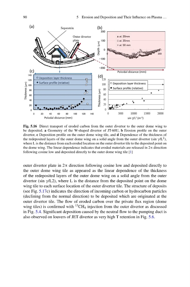
Fig. 5.16 Direct transport of eroded carbon from the outer divertor to the outer dome wing to
be deposited. a Geometry of the W-shaped divertor of JT-60U, b Erosion profile on the outer
divertor, c Deposition profile on the outer dome wing tile, and d Dependence of the thickness of
the redeposited layers of the outer dome wing on a solid angle from the outer divertor (sin γ/L 2 ),
where L is the distance from each eroded location on the outer divertor tile to the deposited point on
the dome wing. The linear dependence indicates that eroded materials are released in 2π direction
following cosine low and deposited directly to the outer dome wing tile [1]
outer divertor plate in 2π direction following cosine low and deposited directly to
the outer dome wing tile as appeared as the linear dependence of the thickness
of the redeposited layers of the outer dome wing on a solid angle from the outer
divertor (sin γ/L2), where L is the distance from the deposited point on the dome
wing tile to each surface location of the outer divertor tile. The structure of deposits
(see Fig. 5.17c) indicates the direction of incoming carbon or hydrocarbon particles
(declining from the normal direction) to be deposited which are originated at the
outer divertor tile. The flow of eroded carbon over the private flux region (dome
wing tiles) is confirmed with
13 CH 4 injection from the outer divertor as discussed
in Fig. 5.4. Significant deposition caused by the neutral flow to the pumping duct is
also observed on louvers of JET divertor as very high T retention in Fig. 5.6.
5 Erosion and Deposition and Their Influence on Plasma …
Fig. 5.16 Direct transport of eroded carbon from the outer divertor to the outer dome wing to
be deposited. a Geometry of the W-shaped divertor of JT-60U, b Erosion profile on the outer
divertor, c Deposition profile on the outer dome wing tile, and d Dependence of the thickness of
the redeposited layers of the outer dome wing on a solid angle from the outer divertor (sin γ/L 2 ),
where L is the distance from each eroded location on the outer divertor tile to the deposited point on
the dome wing. The linear dependence indicates that eroded materials are released in 2π direction
following cosine low and deposited directly to the outer dome wing tile [1]
outer divertor plate in 2π direction following cosine low and deposited directly to
the outer dome wing tile as appeared as the linear dependence of the thickness
of the redeposited layers of the outer dome wing on a solid angle from the outer
divertor (sin γ/L2), where L is the distance from the deposited point on the dome
wing tile to each surface location of the outer divertor tile. The structure of deposits
(see Fig. 5.17c) indicates the direction of incoming carbon or hydrocarbon particles
(declining from the normal direction) to be deposited which are originated at the
outer divertor tile. The flow of eroded carbon over the private flux region (dome
wing tiles) is confirmed with
13 CH 4 injection from the outer divertor as discussed
in Fig. 5.4. Significant deposition caused by the neutral flow to the pumping duct is
also observed on louvers of JET divertor as very high T retention in Fig. 5.6.